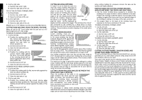
Dewalt DW712 Instruction Manual - Page 12
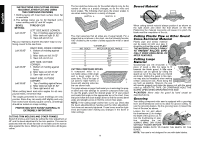
Bowed Material, Cutting Plastic Pipe or Other Round, Cross- al Material, Cutting Large, - saw
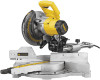 |
View all Dewalt DW712 manuals
Add to My Manuals
Save this manual to your list of manuals |
Page 12 highlights
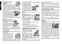
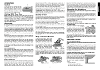
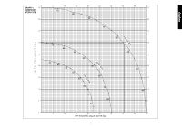
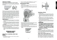
English INSTRUCTIONS FOR CUTTING CROWN MOLDING LAYING FLAT AND USING THE COMPOUND FEATURES 1. Molding laying with broad back surface down flat on saw table. 2. The settings below are for All Standard (U.S.) crown molding with 52° and 38° angles. BEVEL SETTING Left 33.85° TYPE OF CUT LEFT SIDE,INSIDE CORNER: 1. Top of molding against fence 2. Miter table set right 31.62° 3. Save left end of cut Flip your material so that the decorative edge is now facing closest to the saw fence. Left 33.85° RIGHT SIDE, INSIDE CORNER: 1. Bottom of molding against fence 2. Miter table set left 31.62° 3. Save left end of cut Left 33.85° LEFT SIDE, OUTSIDE CORNER: 1. Bottom of molding against fence 2. Miter table set left 31.62° 3. Save right end of cut Left 33.85° RIGHT SIDE, OUTSIDE CORNER: 1. Top of molding against fence 2. Miter table set right 31.62° 3. Save right end of cut When setting bevel and miter angles for all compound miters, remember that: The angles presented for crown moldings are very precise. Since they can easily shift slightly and very few rooms have exactly square corners, all settings should be tested on scrap molding. PRETESTING WITH SCRAP MATERIAL IS EXTREMELY IMPORTANT! CUTTING TRIM MOLDING AND OTHER FRAMES Sketch B shows a joint made by setting the miter adjustment at 45° and the bevel adjustment to the zero position. The wood is positioned with the broad flat side on the table and the narrow edge against the fence. Mitering the boards forms a 90 degree corner. The two sketches below are for four-sided objects only. As the number of sides on a project changes, so do the miter and bevel angles. The following chart gives the proper angles to use when making frames in a variety of shapes. SKETCH A SKETCH B The chart assumes that all sides are of equal length. For a shape that is not shown in the chart, use the following formula: 180° divided by the number of sides equals the miter or bevel angle. - EXAMPLES - NO. SIDES MITER OR BEVEL ANGLE 4 45° 5 36° 6 30° 7 25.7° 8 22.5° 9 20° 10 18° CUTTING COMPOUND MITERS A compound miter is a cut made using a miter angle and a bevel angle at the same time. This is the type of a cut used to make frames or boxes with slanting sides like the one shown here. The graph shown on page 9 will assist you in selecting the proper bevel and miter settings for common compound miter cuts. To use the graph, select the desired angle "A" of your project and locate that angle on the appropriate arc in the chart. From that point follow the chart straight down to find the correct bevel angle and straight across to find the correct miter angle. NOTE: If the cutting angle varies from cut to cut, check that the bevel adjustment/lock handles and the miter adjustment/lock lever are securely tightened. These levers must be tightened and locked after making any changes in the bevel or miter settings. 10 Bowed Material When cutting bowed material always position it as shown on the right above and never like that shown on the left. Positioning the material incorrectly will cause it to pinch the blade near the completion of the cut. Cutting Plastic Pipe or Other Round Cross-Sectional Material Plastic pipe and similar material can be easily cut with your saw. It should be cut just like wood. CLAMP THE MATERIAL OR HOLD FIRMLY TO PREVENT ROLLING ESPECIALLY WHEN USING BEVEL OR MITER FEATURES. Cutting Large Material Occasionally you will encounter a piece of wood a little too large to fit beneath the blade guard. A little extra I clearance can be gained by rolling the guard up out of the way with your thumb as shown. Rolling the guard in this man- ner may also be necessary when making certain compound cuts. Avoid doing this as much as possible. However, the saw will operate properly and make the deeper cut with the guard rolled up. NEVER TIE, TAPE, OR OTHERWISE HOLD THE GUARD OPEN WHEN OPERATING THIS SAW. CAUTION: Never raise the guard by hand except as described above. Grooving Your sliding compound miter saw is equipped with a grooving lever and thumbscrew and nut to allow for groove cutting. To use the grooving feature, flip the grooving lever (I) toward the front of the saw, as shown. Loosen the nut and adjust J the thumbscrew (J) to change the depth of the groove cut. To lock the thumbscrew in posi- tion, retighten the nut. ALWAYS MAKE DRY RUNS WITHOUT POWER BEFORE MAKING FINISH CUTS TO CHECK THE DEPTH OF THE BLADE. NOTE: Your saw is not designed for use with dado blades.
-
 1
1 -
2
-
3
-
4
-
5
-
6
-
 7
7 -
 8
8 -
 9
9 -
 10
10 -
 11
11 -
 12
12 -
 13
13 -
 14
14 -
 15
15 -
 16
16 -
 17
17 -
18
-
19
-
20
-
21
-
22
-
23
-
24
-
25
-
26
-
27
-
28
-
29
-
30
-
31
-
32
-
33
-
34
-
35
-
36
-
37
-
38
-
39
-
40
-
41
-
42
-
43
-
44
 |
 |
