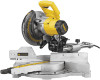
Dewalt DW712 Instruction Manual - Page 8
Automatic Electric Brake, Brushes, Guard Actuation and Visibility - manual
 |
View all Dewalt DW712 manuals
Add to My Manuals
Save this manual to your list of manuals |
Page 8 highlights
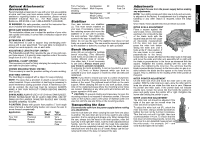
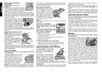
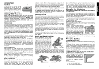
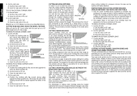
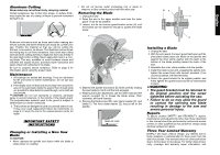
English BEVEL STOPS AND POINTER ADJUSTMENT Adjusting the bevel stop and pointer to 0° Place the saw in the up position (0° bevel, so that the blade is perpendicular to the table of the saw). Push the saw head fully back toward the fence and lock the rail lock knob. Place a square against the saw's base, fence, and blade as shown. Do not touch the tips of the blade teeth with the square because this will cause an inaccurate measurement. Partially loosen the bevel lock handle so that the bevel movement is snug, but not locked. Push the head of saw to the right until the saw head contacts the 0° bevel stop. Adjust the 0˚ bevel stop screw (Q) until the blade is perpendicular to the base of the saw. Completely tighten the bevel lock handle so that the saw head is locked. Make sure that the bevel Q pointer indicates 0° exactly. If it does not, loosen the screw that holds the pointer in place, and gently move the pointer left or right. Retighten the screw after setting the pointer to 0°. Adjusting the bevel stop to 45° left NOTE: Adjust the 45° bevel angles only after performing the 0° bevel angle adjustment and bevel F pointer adjustment. To adjust the left 45° bevel angle, loosen the bevel lock handle (F) and tilt the head to the left. If the pointer does not indicate exactly 45°, turn the bevel stop screw (R1) until the pointer reads 45°. R1 (45˚) R2 (33.85˚) To adjust the crown stop (33.85˚) bevel angle, loosen the bevel lock handle. When the saw is on the stop, if the pointer does not indicate exactly 33.85°, turn the bevel stop screw (R2) until the pointer indicates 33.85°. FENCE ADJUSTMENT Disconnect the saw from the power supply before making any adjustments. To adjust the sliding fence, loosen the K knob (K) and slide the fence in or out. Always adjust the fence to be as close to the blade as practical to provide maximum workpiece support, without interfering with up and down movement of the arm or guard movement. Tighten the knob securely. NOTE: When beveling and mitering, it may, in rare circumstances, be necessary to remove the sliding fence. To remove the fence, fully loosen the fence adjustment knob until the fence is free to slide off. ALWAYS complete a dry run without power before making any cuts. Reinstall the sliding fence and adjust properly for workpiece support. RAIL GUIDE ADJUSTMENT S H Periodically check the rails for any play or clearance. The right rail can be adjusted with the set screw (S) shown on top of the support housing. To reduce clear- ance, rotate the set screw clock- wise gradually while sliding the saw head back and forth. Reduce play while maintaining minimum sliding force. NOTE: The rail lock knob (H) must be loose to allow the saw rails to slide. KERF PLATE ADJUSTMENT Disconnect the saw from the power supply before making any adjustments. Do not use this saw without a kerf plate installed. Replace a kerf plate when it is worn or damaged. To install a new kerf plate: 1. Remove the three screws holding each kerf plate in place. 2. Remove the kerf plates and clean the area beneath. 3. Install the new kerf plates. 4. Replace the screws. To adjust the kerf plate for the desired blade: 1. Loosen but do not remove the three kerf plate screws. 2. Adjust the plates to fit closely to the teeth of the blade. 3. Tighten the 3 screws on each kerf plate. Guard Actuation and Visibility The blade guard on your saw has been designed to automatically raise when the arm is brought down and to lower over the blade when the arm is raised. The guard can be raised by hand when installing or removing saw blades or for inspection of the saw. NEVER RAISE THE BLADE GUARD MANUALLY UNLESS THE SAW IS TURNED OFF. UNPLUG THE SAW BEFORE ANY CLEANING OR ADJUSTMENTS. If the guard becomes dirty, clean with a dry cloth or a waterdampened cloth. CAUTION: Do not use lubricants or cleaners, particularly spray or aerosol cleaners, in the vicinity of the plastic guard. The 6 polycarbonate material used in the guard is subject to deterioration by certain chemicals. NOTE: Certain special cuts will require that you manually raise the guard. See the section titled Cutting Large Material on page 10. The front section of the guard is louvered for visibility while cutting. Although the louvers dramatically reduce flying debris, they are openings in the guard and safety glasses should be worn at all times when viewing through the louvers. Automatic Electric Brake Your saw is equipped with an automatic electric blade brake which stops the saw blade within 5 seconds of trigger release. This brake is not adjustable. On occasion, there may be a delay between the trigger releasing and brake engagement. On rare occasions, the brake may not engage at all and the blade will coast to a stop. If a delay or "skipping" occurs, turn the saw on and off 4 or 5 times. If the condition persists, have the tool serviced by an authorized DEWALT service center or other qualified personnel. Always be sure the blade has stopped before removing it from the kerf. The brake is not a substitute for guards or for ensuring your own safety by giving the saw your complete attention. Brushes Disconnect the saw from the power supply before making any adjustments. Inspect carbon brushes regularly by unplugging tool, removing the motor end cap, lift the brush spring and withdraw the brush assembly. Keep brushes clean and sliding freely in their guides. Always replace a used brush in the same orientation in the holder as it was prior to its removal. Carbon brushes have varying symbols stamped into their sides, and if the brush is worn down to approximately 1/2 inch, the spring will no longer exert pressure and brushes must be replaced. Use only identical DEWALT brushes. Use of the correct grade of brush is essential for proper operation of electric brake. New brush assemblies are available at DEWALT service centers. The tool should be allowed to "run in" (run at no load) for 10 minutes before use to seat new brushes. The electric brake may be erratic in operation until the brushes are properly seated (worn in). Always replace the motor end cap after inspecting or servicing the brushes. While "running in" DO NOT TIE, TAPE, OR OTHERWISE LOCK THE TRIGGER SWITCH ON. HOLD BY HAND ONLY.
-
 1
1 -
2
-
 3
3 -
 4
4 -
 5
5 -
 6
6 -
 7
7 -
 8
8 -
 9
9 -
 10
10 -
 11
11 -
 12
12 -
 13
13 -
14
-
15
-
16
-
17
-
18
-
19
-
20
-
21
-
22
-
23
-
24
-
25
-
26
-
27
-
28
-
29
-
30
-
31
-
32
-
33
-
34
-
35
-
36
-
37
-
38
-
39
-
40
-
41
-
42
-
43
-
44
 |
 |
