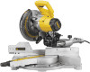
Dewalt DW712 Instruction Manual - Page 6
Electrical Connection and Motor, Unpacking Your Saw, Familiarization, Controls, Specifications - miter saw
 |
View all Dewalt DW712 manuals
Add to My Manuals
Save this manual to your list of manuals |
Page 6 highlights
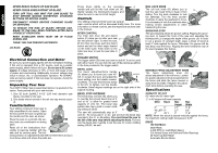
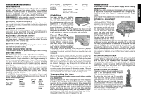
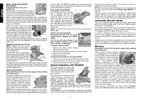
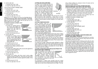
English NEVER REACH IN BACK OF SAW BLADE. NEVER CROSS ARMS IN FRONT OF BLADE. TURN OFF TOOL AND WAIT FOR SAW BLADE TO STOP BEFORE MOVING WORKPIECE, CHANGING SETTINGS OR MOVING HANDS. DISCONNECT POWER BEFORE CHANGING BLADE OR SERVICING. TO REDUCE THE RISK OF INJURY, RETURN CARRIAGE TO THE FULL REAR POSITION AFTER EACH CROSSCUT OPERATION. REAR STABILIZER BARS MUST BE IN PLACE DURING USE. THINK! YOU CAN PREVENT ACCIDENTS. ON BASE: Electrical Connection and Motor Be sure your power supply agrees with the nameplate marking. If this unit is operated from a DC source, such as a welder power supply, switch failure will occur. Do not use a DC power supply. A voltage decrease of 10% or more will cause a loss of power and overheating. Additionally, incorrect voltage may result in shock, fire, or unpredictable operation. All DEWALT tools are factory tested. If this tool does not operate, check the power supply. Unpacking Your Saw Your DW712 Miter Saw is assembled before it is packed in the carton. Parts packed with your saw include 1. One 30 tooth DEWALT 8-1/2" (216 mm) diameter saw blade, mounted on the saw 2. One blade wrench stored in the rail end cap wrench pocket. Familiarization Your sliding compound miter saw is fully assembled in the carton. Open the box and lift the saw out gently by the handle and the rails, as shown. Place the saw on a smooth, flat surface such as a workbench or strong table. Read all of the instructions thoroughly to become familiar with the saw and its various parts. The following section on adjustments will refer to these terms and you must know what and where the parts are. Press down lightly on the operating A handle and pull out the lock down pin (A). Gently release the downward pressure and allow the arm to rise to its full height. Controls Your sliding compound miter saw has several main controls which will be discussed briefly here. For more information on these controls, see the respective sections later in the manual. MITER CONTROL The miter lock lever (B) and detent button (C) allow you to miter your saw D 50° left and 60° right. To miter the saw, lift the miter lock lever, push the detent button and set the miter angle desired C on the miter scale. Push down on the miter lock lever to lock the saw table in B place. TRIGGER SWITCH The trigger switch (D) turns your saw on and off. It can be used with either hand. You can lock the saw off by placing a padlock in the hole provided in the trigger switch. BEVEL LOCK The bevel adjustment/lock handle (F) allows you to bevel your saw 45° UNLOCK left. To loosen the lever and adjust the bevel setting, turn the handle counter- clockwise. The saw head bevels easily to the left. To tighten, turn the handle F LOCK clockwise. Bevel degree markings are on the right side of the support housing. BEVEL STOP OVERRIDE The bevel stop override (G) allows you to override the pre-set bevel stop at 0˚ and at 45˚ to allow for greater bevel capacity of -2˚to 48˚. The bevel stop system also has a built in crown mold- ing setting at 33.85˚. G The saw will automatically stop at 0˚ and 45˚. To move past 0˚ or 45˚, pull and turn the bevel stop override to the -2˚ or 48˚setting. You must bevel the saw to the left of the zero stop before adjusting the knob. Pull and turn the bevel stop override to set the saw for crown molding setting (33.85˚) as well. RAIL LOCK KNOB The rail lock knob (H) allows you to H lock the saw head firmly to keep it from sliding. Turn the knob clockwise to lock the sawhead. Turn the knob counter- clockwise to allow the sawhead to move. It is necessary to lock the sawhead when making certain adjustments or when transporting the saw. GROOVING STOP The grooving stop allows for groove cutting. Flipping the grooving lever (I) toward the front of the saw and adjusting the thumbscrew (J) changes the depth of the groove cut. In order to cut a groove of constant depth, place a block of wood at least 2" wide against the fence. Otherwise, the groove will be less deep near the fence. Flipping the lever toward the rear of the saw bypasses this feature. J I MOVABLE FENCE ADJUSTMENT KNOB The fence adjustment knob (K) K allows adjustment of the left fence. Loosen the plastic adjustment knob located behind the fence and slide the fence toward or away from the blade. Retighten the adjustment knob before operating the saw. Specifications CAPACITY OF CUT 50° miter left, 60° miter right -2˚ to 48 degree left bevel capacity Miter Bevel Max Max Height Width 0° 0° 2.7" 11.8" 45 L&R° 0° 2.7" 8.3" 0° 45° L 2" 11.8" NOTE: When thin stock is placed vertically against the fence, the maximum cutting height increases to 3.25". DRIVE 120 Volt Motor 2200 Watts 5,400 RPM no load Blade Speed Cut Helical Gears with Ball and Roller Bearings 30 Tooth Carbide Blade Automatic Electric Brake 4
-
 1
1 -
 2
2 -
 3
3 -
 4
4 -
 5
5 -
 6
6 -
 7
7 -
 8
8 -
 9
9 -
 10
10 -
 11
11 -
 12
12 -
13
-
14
-
15
-
16
-
17
-
18
-
19
-
20
-
21
-
22
-
23
-
24
-
25
-
26
-
27
-
28
-
29
-
30
-
31
-
32
-
33
-
34
-
35
-
36
-
37
-
38
-
39
-
40
-
41
-
42
-
43
-
44
 |
 |
