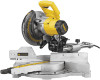
Dewalt DW712 Instruction Manual - Page 7
Optional Attachments, Accessories, Adjustments, Stabilizer, Bench Mounting, Transporting the Saw - blade size
 |
View all Dewalt DW712 manuals
Add to My Manuals
Save this manual to your list of manuals |
Page 7 highlights
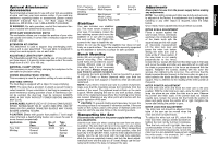
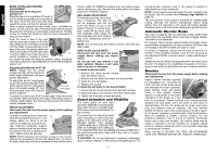
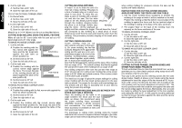
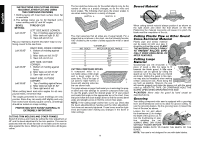
Optional Attachments/ Accessories Recommended accessories for use with your tool are available at extra cost from your local service center. If you need any assistance regarding blades or accessories, please contact DEWALT Industrial Tool Co., 701 East Joppa Road, Baltimore, MD 21286 or call 1-800-4-DEWALT (433-9258). WARNING: For safe operation, read all the instruction literature included with attachments/accessories. MITER SAW WORKSTATION: DW723 The workstation allows you to adjust the position of your miter saw quickly and easily. It comes with a workpiece support and a length stop. EXTENSION KIT: DW7080 This attachment is used to support long overhanging workpieces and is user assembled. Your saw table is designed to accept two work supports, one on each side. ADJUSTABLE LENGTH STOP: DW7051 The Adjustable Length Stop requires the use of one work support (see above). It is used to make repetitive cuts of the same length from 0 to 42" (0 to 106 cm). MATERIAL CLAMP: DW7082 This accessory is used for firmly clamping the workpiece to the saw table for precision cutting. CROWN MOLDING FENCE: DW7084 This accessory is used for precision cutting of crown molding. DUST BAG: DW7053 The Dust Bag is equipped with a zipper for easy emptying. NOTE: The spout has a provision to attach a vacuum hose to collect sawdust. Proper orientation of dust bag is necessary to avoid interference during operation of saw. If interference cannot be avoided, the dust bag must be removed. ALWAYS MAKE A DRY RUN WITHOUT POWER BEFORE MAKING ANY CUTS. SAW BLADES: ALWAYS USE 8-1/2" (216mm) SAW BLADES. SPEED RATING MUST BE AT LEAST 6000 RPM. USE OF SMALLER OR LARGER DIAMETER BLADES MAY CAUSE SEVERE DAMAGE TO SAW. CAUTION: Blades with greater than positive 5˚ hook angle (rake) that lack a depth-limiting feature can cause the saw to move forward unexpectedly. Application Blade Desc. No. of Type Teeth of Cut Fine Trim Molding Precision Ground 40-60 Very Smooth Carbide Splinter Free Trim, Framing, Pressure Treated Decking Aluminum Combination 30 Multi-Purpose Non-Ferrous 60 Metal Cutting Negative Rake Teeth Smooth Fast Cut - Stabilizer Your saw includes one stabilizer (L). This must remain installed on your saw. If necessary, loosen the two retaining screws and move the stabilizer in or out until it contacts the work surface. Then tighten the screws in the base to fasten the sta- L bilizer. Do not use the saw if the stabilizer bar does not rest firmly on a work surface. The saw must be securely supported by the stabilizer or bolted to a surface for safe operation. Bench Mounting Holes (M) are provided to facilitate bench mounting. (Two differently M sized holes are provided to accom- modate different sizes of screws. Use either hole; it is not necessary to use both.) Always mount your saw firmly to prevent movement. To enhance the tool's portability, it can be mounted to a piece of 1/2" (12.7mm) or thicker plywood which can then be clamped to your work support or moved to other job sites and reclamped. NOTE: If you elect to mount your saw to a piece of plywood, make sure that the mounting screws don't protrude from the bottom of the wood. The plywood must sit flush on the work support. When clamping the saw to any work surface, clamp only on the clamping bosses where the mounting screw holes are located. Clamping at any other point will interfere with the proper operation of the saw. CAUTION: To prevent binding and inaccuracy, be sure the mounting surface is not warped or otherwise uneven. If the saw rocks on the surface, place a thin piece of material under one saw foot until the saw sits firmly on the mounting surface. Transporting the Saw Disconnect the saw from the power supply before making any adjustments. Use the lock down pin when carrying the saw from one place to another. The lock down pin is not to be used for any cutting operation; it is for carrying and storage only. When transporting the saw, always lock the head in the down position, miter the saw fully to the right (60° miter), lock the miter adjustment/lock handle, lock the rail lock knob with the head fully extended, slide the fences completely inward, and lock the bevel adjustment/lock lever with the saw at a 0° bevel. Always use the carrying hand holds in the base to transport the saw. 5 Adjustments Disconnect the saw from the power supply before making any adjustments. NOTE: Your sliding compound miter saw is fully and accurately adjusted at the factory. If readjustment due to shipping and handling or any other reason is required, follow the steps below. Once made, these adjustments should remain accurate. MITER SCALE ADJUSTMENT Place a square against the saw's base, fence, and blade, as shown. Do not touch the tips of the blade teeth with the square because this will cause O an inaccurate measurement. Lift the miter lock lever and press the miter lock button. Swing the miter arm until it locks at the 0° miter position. If the saw blade is not exactly N perpendicular to the fence, loosen the four screws (N) that hold the miter scale to the base and move the scale and miter arm assembly left or right until the blade is perpendicular to the fence as measured with the square. Retighten the screws, starting with the outer two screws, then tightening the inner two. You will know that the blade is perpendicular (square) to the fence when no gap is vi- sible between the blade and the square or the fence and the square. Pay no attention to the reading of the miter pointer at this point. MITER POINTER ADJUSTMENT Lift the miter lock lever and move the miter arm to the zero position. With the miter lock lever open, allow the miter latch to snap into place as you rotate the miter arm to zero. Observe the pointer and miter scale. If the pointer does not indicate exactly zero, loosen the screw (O) that holds the pointer in place and gently move the pointer left or right. Retighten the screw after setting the pointer to zero. MITER LOCK ROD ADJUSTMENT The miter lock rod should be adjusted if the table of the saw can be moved when the miter lock lever is locked-down. To adjust the miter lock rod (P), unlock the P miter lock lever. Using a slotted screwdriver, tighten the lock rod by turning it clockwise. Turn the lock rod until it is tight, then turn counterclockwise 1/4 turn. To ensure that the lock lever is functioning properly, re-lock the miter lock to a non-detented measurement on the miter scale -for example, 34°- and verify that the table will not rotate. English
-
 1
1 -
 2
2 -
 3
3 -
 4
4 -
 5
5 -
 6
6 -
 7
7 -
 8
8 -
 9
9 -
 10
10 -
 11
11 -
 12
12 -
13
-
14
-
15
-
16
-
17
-
18
-
19
-
20
-
21
-
22
-
23
-
24
-
25
-
26
-
27
-
28
-
29
-
30
-
31
-
32
-
33
-
34
-
35
-
36
-
37
-
38
-
39
-
40
-
41
-
42
-
43
-
44
 |
 |
