Epson C31CA85090 Reference Guide - Page 39
Setting the DIP Switches, Setting Procedure
 |
View all Epson C31CA85090 manuals
Add to My Manuals
Save this manual to your list of manuals |
Page 39 highlights
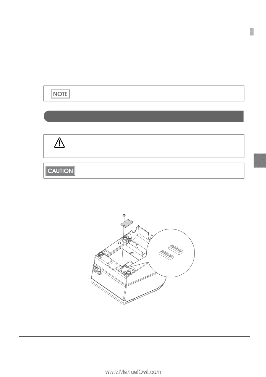
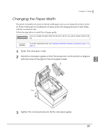
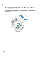
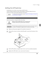
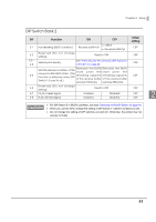
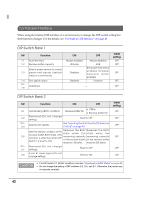
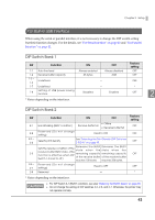
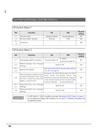
Chapter 2 Setup Setting the DIP Switches On this printer, you can make various settings with DIP switches. The DIP switches are already set for the current interfaces. Change the setting if necessary. Functions of the DIP switches differ depending on the interface. For models with the buzzer function, see also "Setting the Internal Buzzer (for Model with an Internal Buzzer)" on page 65. Setting Procedure Follow the steps below to change the DIP switch settings. Before you remove the DIP switch cover, turn the printer off. Otherwise, a short-circuit may cause the printer to malfunction. CAUTION 2 DIP switch settings are enabled only when the power is turned on or the printer is reset via the interface. If the settings are changed after that, the functions will not change. 1 Make sure the power supply for the printer is turned off. 2 Unscrew the screw to remove the DIP switch cover from the base of the printer. DIP switch bank 2 DIP switch bank 1 3 Set the DIP switches, using the tip of a tool, such as a small screwdriver. 4 Replace the DIP switch cover, and screw it in place. 39
-
 1
1 -
2
-
3
-
4
-
5
-
6
-
7
-
8
-
9
-
10
-
11
-
12
-
13
-
14
-
15
-
16
-
17
-
18
-
19
-
20
-
21
-
22
-
23
-
24
-
25
-
26
-
27
-
28
-
29
-
30
-
31
-
32
-
33
-
 34
34 -
 35
35 -
 36
36 -
 37
37 -
 38
38 -
 39
39 -
 40
40 -
 41
41 -
 42
42 -
 43
43 -
 44
44 -
45
-
46
-
47
-
48
-
49
-
50
-
51
-
52
-
53
-
54
-
55
-
56
-
57
-
58
-
59
-
60
-
61
-
62
-
63
-
64
-
65
-
66
-
67
-
68
-
69
-
70
-
71
-
72
-
73
-
74
-
75
-
76
-
77
-
78
-
79
-
80
-
81
-
82
-
83
-
84
-
85
-
86
-
87
-
88
-
89
-
90
-
91
-
92
-
93
-
94
-
95
-
96
-
97
-
98
-
99
-
100
-
101
-
102
-
103
-
104
-
105
-
106
-
107
-
108
-
109
-
110
-
111
-
112
-
113
-
114
-
115
-
116
-
117
-
118
-
119
-
120
-
121
-
122
-
123
-
124
-
125
-
126
-
127
-
128
-
129
-
130
-
131
-
132
-
133
-
134
-
135
-
136
-
137
-
138
-
139
-
140
-
141
-
142
-
143
-
144
-
145
-
146
-
147
-
148
-
149
-
150
-
151
-
152
-
153
-
154
-
155
-
156
-
157
-
158
 |
 |