Epson U220B Technical Reference - Page 43
Stand alone, Y-connection - dip switch
 |
View all Epson U220B manuals
Add to My Manuals
Save this manual to your list of manuals |
Page 43 highlights
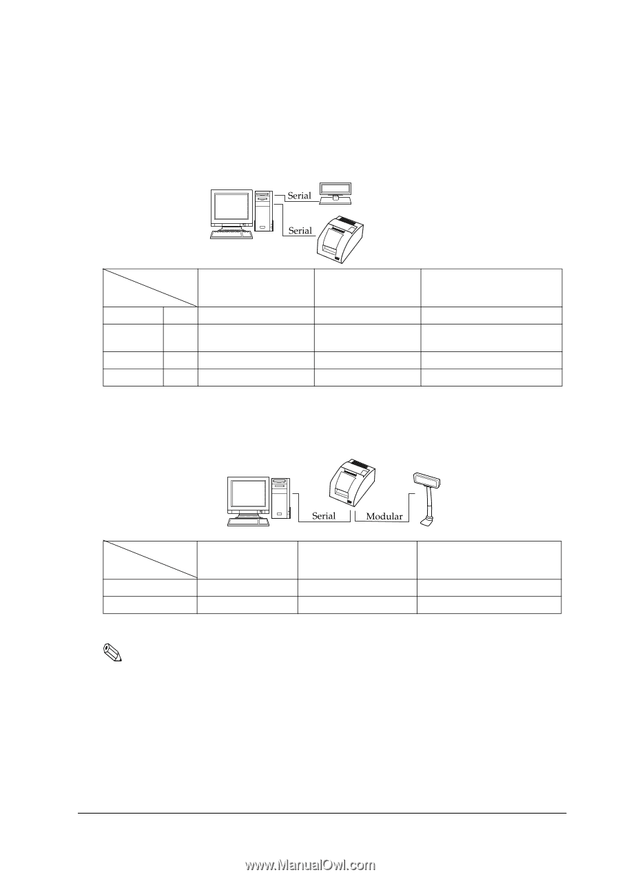
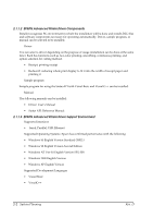
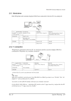
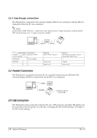
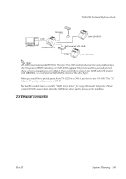
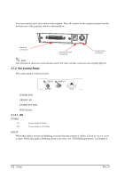
TM-U220 Technical Reference Guide 2.3.1 Stand alone Both TM printer and customer display (DM-D) are connected to the host PC via serial port. 2 1 Application XON/XOFF TM side control (except OPOS) control setting DTR/DSR (DOS, OPOS, Visual C) XON/XOFF 1 Type A or B - 2 DM-D500: A,B - Other DM-D: not available DTR/DSR 1 - Type A or B 2 - Type A or B RTS/CTS (DOS, Windows driver, Visual C, Visual Basic, MSComm) - - Type B Type B 2.3.2 Y-connection TM printer is connected to the host PC via serial port and the customer display (DM-D) is connected to TM printer via a modular connector. Application XON/XOFF TM side control (except OPOS) control setting XON/XOFF Not available DTR/DSR - DTR/DSR (DOS, OPOS, Visual C) - Type B (*) (*) When RTS/CTS control is used between the TM and DM. RTS/CTS (DOS, Windows driver, Visual C, Visual Basic, MSComm) - Type B Note: When you would like to provide power from TM-U220 to a DM-D, you have to use "PS-180." The "AC Adapter C" can't provide power to a DM-D. You need to use the UB-S09 interface when you use a modular connector. On the DM-D (DM-D500 etc...) which has DIP switch to select Y-type connection, confirm that the DIP switch has been set "Y-type connection: Enable." Rev. D System Planning 2-7
-
 1
1 -
2
-
3
-
4
-
5
-
6
-
7
-
8
-
9
-
10
-
11
-
12
-
13
-
14
-
15
-
16
-
17
-
18
-
19
-
20
-
21
-
22
-
23
-
24
-
25
-
26
-
27
-
28
-
29
-
30
-
31
-
32
-
33
-
34
-
35
-
36
-
37
-
 38
38 -
 39
39 -
 40
40 -
 41
41 -
 42
42 -
 43
43 -
 44
44 -
 45
45 -
 46
46 -
 47
47 -
 48
48 -
49
-
50
-
51
-
52
-
53
-
54
-
55
-
56
-
57
-
58
-
59
-
60
-
61
-
62
-
63
-
64
-
65
-
66
-
67
-
68
-
69
-
70
-
71
-
72
-
73
-
74
-
75
-
76
-
77
-
78
-
79
-
80
-
81
-
82
-
83
-
84
-
85
-
86
-
87
-
88
-
89
-
90
-
91
-
92
-
93
-
94
-
95
-
96
-
97
-
98
-
99
-
100
-
101
-
102
-
103
-
104
-
105
-
106
-
107
-
108
-
109
-
110
-
111
-
112
-
113
-
114
-
115
-
116
-
117
-
118
-
119
-
120
-
121
-
122
-
123
-
124
-
125
-
126
-
127
-
128
-
129
-
130
-
131
-
132
-
133
-
134
-
135
-
136
-
137
-
138
-
139
-
140
-
141
-
142
-
143
-
144
-
145
-
146
-
147
-
148
-
149
-
150
-
151
-
152
-
153
-
154
-
155
-
156
-
157
-
158
-
159
-
160
-
161
-
162
-
163
-
164
 |
 |