Epson U220B Technical Reference - Page 77
Serial Interface model, 4.8.2, Parallel Interface Models, 4.8.3, USB Interface Models - u220 dip switch
 |
View all Epson U220B manuals
Add to My Manuals
Save this manual to your list of manuals |
Page 77 highlights
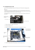
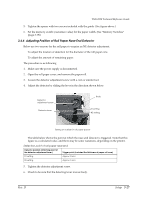
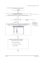
TM-U220 Technical Reference Guide 3.4.8.1 Serial Interface model Before connecting any of the cables, make sure that both the printer and the host PC are turned off. 1. Plug the cable connector securely into the printer's interface connector. 2. If the cable connector has screws on it, tighten the screws on both sides of the connector. 3. If your interface connector has a grounding wire, attach it to the printer using the screw labeled FG, which is next to the interface connector. 4. Attach the other end of the cable to the host PC. Note: When using serial interface, you need to adjust serial communication using the DIP switches. See "Adjusting the DIP Switches" (page 3-15) for details. When using serial interface, see "Serial Connection" in Chapter 2 also. 3.4.8.2 Parallel Interface Models 1. Press the connector on the end of the interface cable firmly into the interface connector on the connector panel. 2. Press down the clips on either side of the connector to lock it in place. 3. For interface cables equipped with a ground line, attach the ground line to the screw hole marked "FG" on the printer. 4. Connect the other end of the interface cable to the host computer. 3.4.8.3 USB Interface Models 1. Attach the locking wire saddle at the location shown in the figure below. 2. Hook the USB cable through the locking wire saddle, as shown in the figure below. Rev. D Setup 3-31
-
 1
1 -
2
-
3
-
4
-
5
-
6
-
7
-
8
-
9
-
10
-
11
-
12
-
13
-
14
-
15
-
16
-
17
-
18
-
19
-
20
-
21
-
22
-
23
-
24
-
25
-
26
-
27
-
28
-
29
-
30
-
31
-
32
-
33
-
34
-
35
-
36
-
37
-
38
-
39
-
40
-
41
-
42
-
43
-
44
-
45
-
46
-
47
-
48
-
49
-
50
-
51
-
52
-
53
-
54
-
55
-
56
-
57
-
58
-
59
-
60
-
61
-
62
-
63
-
64
-
65
-
66
-
67
-
68
-
69
-
70
-
71
-
 72
72 -
 73
73 -
 74
74 -
 75
75 -
 76
76 -
 77
77 -
 78
78 -
 79
79 -
 80
80 -
 81
81 -
 82
82 -
83
-
84
-
85
-
86
-
87
-
88
-
89
-
90
-
91
-
92
-
93
-
94
-
95
-
96
-
97
-
98
-
99
-
100
-
101
-
102
-
103
-
104
-
105
-
106
-
107
-
108
-
109
-
110
-
111
-
112
-
113
-
114
-
115
-
116
-
117
-
118
-
119
-
120
-
121
-
122
-
123
-
124
-
125
-
126
-
127
-
128
-
129
-
130
-
131
-
132
-
133
-
134
-
135
-
136
-
137
-
138
-
139
-
140
-
141
-
142
-
143
-
144
-
145
-
146
-
147
-
148
-
149
-
150
-
151
-
152
-
153
-
154
-
155
-
156
-
157
-
158
-
159
-
160
-
161
-
162
-
163
-
164
 |
 |
