Epson U220B Technical Reference - Page 67
Memory Switch Setup Mode - u220 power supply
 |
View all Epson U220B manuals
Add to My Manuals
Save this manual to your list of manuals |
Page 67 highlights
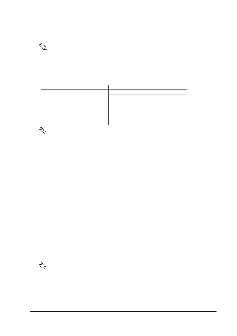
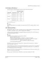
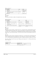
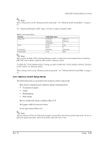
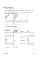
TM-U220 Technical Reference Guide Note: These setting can be set by "Memory switch setup mode." See "Memory Switch Setup Mode" on page 321. See "Adjusting Roll paper width" (page 3-26) also to adjust roll paper width. Serial communication Function baud rate Parity Handshake Data length Selectable value 1200 bps 4800 bps 19200 bps None Even DSR/DTR 7 bit 2400 bps 9600 bps -Odd -XON/XOFF 8 bit Note: There are two methods, DIP switch and Memory switch, to adjust the serial communication conditions. DIP SW2 selects which is effective, DIP switch or Memory switch. To enable the "Serial communication" setting, you have to adjust the "Serial interface selection" function of DIP switch 2 to "Memory switch." These settings can be set by "Memory switch setup mode." See "Memory Switch Setup Mode" on page 321. 3.4.4 Memory Switch Setup Mode The following items are specified in the memory switch setup mode: ❏ Basic Serial communication condition (Serial communication) • Transmission speed • Parity • Handshaking • Data length ❏ Receive buffer full release condition (Msw 8-7) ❏ Roll paper width (Customize value) ❏ Cover open status (Msw 8-5) Note: All new settings will be lost if the power supply is turned off in the memory switch setup mode. Be sure to follow the proper procedure, and turn the power off at the correct time. Rev. D Setup 3-21
-
 1
1 -
2
-
3
-
4
-
5
-
6
-
7
-
8
-
9
-
10
-
11
-
12
-
13
-
14
-
15
-
16
-
17
-
18
-
19
-
20
-
21
-
22
-
23
-
24
-
25
-
26
-
27
-
28
-
29
-
30
-
31
-
32
-
33
-
34
-
35
-
36
-
37
-
38
-
39
-
40
-
41
-
42
-
43
-
44
-
45
-
46
-
47
-
48
-
49
-
50
-
51
-
52
-
53
-
54
-
55
-
56
-
57
-
58
-
59
-
60
-
61
-
 62
62 -
 63
63 -
 64
64 -
 65
65 -
 66
66 -
 67
67 -
 68
68 -
 69
69 -
 70
70 -
 71
71 -
 72
72 -
73
-
74
-
75
-
76
-
77
-
78
-
79
-
80
-
81
-
82
-
83
-
84
-
85
-
86
-
87
-
88
-
89
-
90
-
91
-
92
-
93
-
94
-
95
-
96
-
97
-
98
-
99
-
100
-
101
-
102
-
103
-
104
-
105
-
106
-
107
-
108
-
109
-
110
-
111
-
112
-
113
-
114
-
115
-
116
-
117
-
118
-
119
-
120
-
121
-
122
-
123
-
124
-
125
-
126
-
127
-
128
-
129
-
130
-
131
-
132
-
133
-
134
-
135
-
136
-
137
-
138
-
139
-
140
-
141
-
142
-
143
-
144
-
145
-
146
-
147
-
148
-
149
-
150
-
151
-
152
-
153
-
154
-
155
-
156
-
157
-
158
-
159
-
160
-
161
-
162
-
163
-
164
 |
 |