Epson U220B Technical Reference - Page 76
Connecting the Printer to the Host PC / POS Terminal - ethernet printer setup
 |
View all Epson U220B manuals
Add to My Manuals
Save this manual to your list of manuals |
Page 76 highlights
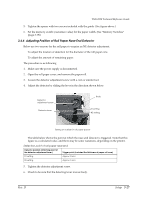
6. When you select partial cut (default), you have to adjust the dowel to the right, as shown. When you select full cut, you have to adjust the dowel to left as shown. Partial cut Full cut 7. Tighten the two screws. 8. Set again the roll paper cover, and set the shaft which is taken out in step 3. 9. Install roll paper 10. Execute the self test to confirm the cutter action. (See "Self Test Procedure" (page 3-40)) 3.4.8 Connecting the Printer to the Host PC / POS Terminal All cables are connected to the connector panel located on the lower rear side of the printer. Drawer kick connector FG FG DK DC24V Interface connector Power supply connector Connector panel Note: The figure above shows the connector panel for the serial interface model printer. The shape of the interface connector varies according to the type of interface used. Be sure to turn off the power supply for both the printer and the host computer unit before connecting the various cables. You need an appropriate serial, parallel, USB, or Ethernet interface cable to connect your computer to the printer. For the serial model, it is important that you use a null modem cable, not any other serial cable, and for the parallel model use an IEEE 1284 cable. 3-30 Setup Rev. D
-
 1
1 -
2
-
3
-
4
-
5
-
6
-
7
-
8
-
9
-
10
-
11
-
12
-
13
-
14
-
15
-
16
-
17
-
18
-
19
-
20
-
21
-
22
-
23
-
24
-
25
-
26
-
27
-
28
-
29
-
30
-
31
-
32
-
33
-
34
-
35
-
36
-
37
-
38
-
39
-
40
-
41
-
42
-
43
-
44
-
45
-
46
-
47
-
48
-
49
-
50
-
51
-
52
-
53
-
54
-
55
-
56
-
57
-
58
-
59
-
60
-
61
-
62
-
63
-
64
-
65
-
66
-
67
-
68
-
69
-
70
-
 71
71 -
 72
72 -
 73
73 -
 74
74 -
 75
75 -
 76
76 -
 77
77 -
 78
78 -
 79
79 -
 80
80 -
 81
81 -
82
-
83
-
84
-
85
-
86
-
87
-
88
-
89
-
90
-
91
-
92
-
93
-
94
-
95
-
96
-
97
-
98
-
99
-
100
-
101
-
102
-
103
-
104
-
105
-
106
-
107
-
108
-
109
-
110
-
111
-
112
-
113
-
114
-
115
-
116
-
117
-
118
-
119
-
120
-
121
-
122
-
123
-
124
-
125
-
126
-
127
-
128
-
129
-
130
-
131
-
132
-
133
-
134
-
135
-
136
-
137
-
138
-
139
-
140
-
141
-
142
-
143
-
144
-
145
-
146
-
147
-
148
-
149
-
150
-
151
-
152
-
153
-
154
-
155
-
156
-
157
-
158
-
159
-
160
-
161
-
162
-
163
-
164
 |
 |
