Harman Kardon AVR 240 Owners Manual - Page 20
System Setup - protect
 |
View all Harman Kardon AVR 240 manuals
Add to My Manuals
Save this manual to your list of manuals |
Page 20 highlights
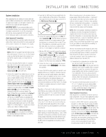
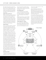
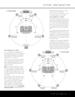
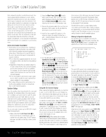
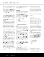
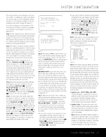
SYSTEM CONFIGURATION Since subwoofers produce nondirectional sound, they may be placed almost anywhere in a room. Actual placement should be based on room size and shape and the type of subwoofer used. One method of finding the optimal location for a subwoofer is to begin by placing it in the front of the room, about six inches from a wall, or near the front corner of the room. Another method is to temporarily place the subwoofer at your normal listening position, and then walk around the room until you find a spot where the subwoofer sounds best. Place the subwoofer in that spot. You should also follow the instructions of the subwoofer's manufacturer, or you may wish to experiment with the best location for a subwoofer in your listening room. NOTES ON SPEAKER PLACEMENT: 1. The limitations of your listening room, including the placement of walls and furniture, may make it difficult to follow the speaker placement suggestions shown above. Depending on the specific layout of the room, here are some ways to compensate for unusual conditions: • Try to follow the suggested placement, but move the speakers within a few feet from the preferred locations. • Regardless of where they are placed, always try to make certain that the main surround speakers are the same distance from the front speakers. (For example, try not to have the right surround speaker further back into the room than the left surround speaker.) • If it is not possible to wall-mount or place speakers on a shelf, consider the use of optional floor stands, available for many speakers. 2. When using ceiling-mounted in-wall speakers, follow the same guidelines shown for conventional floor or shelf-mounted speakers. System Setup Once the speakers have been placed in the room and connected, the remaining steps in the setup process are to configure each source input to match the physical connections you have made, select a surround mode and run the EzSet+ procedure, which will automatically program the AVR 240's bass management system for the type of speakers used in your system, calibrate the output levels, and set the delay times used by the surround sound processor. You are now ready to power up the AVR 240 to begin these final adjustments. 1. Make certain that the AC Power Cord fl is firmly inserted into an unswitched AC outlet. To maintain the unit's safety rating, DO NOT replace the power cord with one that has a lower current capacity. 2. Press the Main Power Switch 1 in until it latches and the word "OFF" on the top of the switch disappears inside the front panel. Note that the Power Indicator 2 will turn amber, indicating that the unit is in the Standby mode. 3. Remove the protective plastic film from the frontpanel lens. If left in place, the film will affect the performance of your remote control. 4. Install the three supplied AAA batteries in the remote as shown. Be certain to follow the (+) and (-) polarity indicators that are on the top of the battery compartment. 5. Turn the AVR 240 on either by pressing the Standby/On Switch 2 on the front panel, or via the remote by pressing the Power On Button d, the AVR Selector f or any of the Input Selectors deg. When the unit is turned on, the entire list of options will briefly light for both the Input Indicators Ú and the Surround Mode Indicators ˆ. After a few seconds, the majority of those indicators will go dark, leaving only the indications for the active surround mode and input illuminated. The Display Lines Ùı will display the unit's status, the Power Indicator 2 will turn blue, and the accent light inside the Volume Control Ò will also light up to remind you that the unit is turned on. Using the On-Screen Display When making the following adjustments, you may find it easier to use the AVR 240's on-screen display system. These easy-to-read displays give you a clear picture of the current status of the unit and make it easy to see which selection you are making. To view the on-screen menus, make certain that you have made a connection from the Video or S-Video Monitor Out Jack cV on the rear panel to the composite or S-video input of your TV or projector. In order to view the AVR 240's displays, the correct video source must be selected on the video display. The on-screen menus are not available when a component video display is in use. IMPORTANT NOTE: When viewing the on-screen menus using a CRT-based projector, plasma display or any direct-view CRT monitor or television, it is important that they not be left on the screen for an extended period of time. The constant display of a static image such as these menus or other still images may cause the image to be permanently "burned into" the projection tubes, plasma screen or CRT. This type of damage is not covered by the AVR 240 warranty and may not be covered by the projector/TV set's warranty. The AVR 240 has two on-screen display modes, "Semi-OSD" and "Full-OSD." When making configuration adjustments, it is recommended that the full-OSD mode be used. This will place a menu on the screen, making it easier to view the available options. Making Configuration Adjustments The full-OSD system is available by pressing the OSD Button v. When this button is pressed, the MASTER MENU (Figure 1) will appear, and adjustments are made from the individual menus. ** MASTER MENU ** INPUT SETUP AUDIO SETUP SURROUND SELECT EzSet+ MANUAL SETUP ADVANCED Figure 1 The semi-OSD system is also available, allowing you to make adjustments directly, by pressing the appropriate buttons on the front panel or remote control for the specific parameter to be adjusted. For example, to change the digital input for any of the sources, press the Digital Select Button q and then press the ⁄/¤ Buttons n to scroll through the list of options as they appear in the on-screen display or the Upper Display Line P. To use the full-OSD menu system, press the OSD Button v. When the menu is on the screen, press the ⁄/¤ Buttons n until the on-screen › cursor is next to the item you wish to adjust, and then press the Set Button p to adjust that item. The menus will remain on the screen for 20 seconds, and then they will "time-out" and disappear from the screen. The time-out may be increased to as much as 50 seconds by going to the ADVANCED SELECT menu, and changing the item titled FULL OSD TIME OUT (see page 42). When the full-OSD menu system is used, OSD ON will appear in the Upper Display Line P to remind you that a video display must be used. When the semi-OSD system is used in conjunction with the discrete configuration buttons, the on-screen display will show the current menu selection. That selection will also be shown in the Upper Display Line P or the Lower Display Line ı, depending on which parameter is being adjusted. 20 SYSTEM CONFIGURATION
-
 1
1 -
2
-
3
-
4
-
5
-
6
-
7
-
8
-
9
-
10
-
11
-
12
-
13
-
14
-
 15
15 -
 16
16 -
 17
17 -
 18
18 -
 19
19 -
 20
20 -
 21
21 -
 22
22 -
 23
23 -
 24
24 -
 25
25 -
26
-
27
-
28
-
29
-
30
-
31
-
32
-
33
-
34
-
35
-
36
-
37
-
38
-
39
-
40
-
41
-
42
-
43
-
44
-
45
-
46
-
47
-
48
-
49
-
50
-
51
-
52
-
53
-
54
-
55
-
56
-
57
-
58
-
59
-
60
-
61
-
62
-
63
-
64
 |
 |
