Harman Kardon AVR 240 Owners Manual - Page 9
Digital Media Player DMP Connector - 7 1 channel receiver
 |
View all Harman Kardon AVR 240 manuals
Add to My Manuals
Save this manual to your list of manuals |
Page 9 highlights
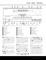
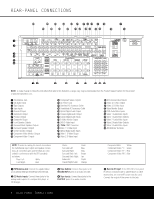
REAR-PANEL CONNECTIONS § Remote IR Output: This connection permits the IR sensor in the receiver to serve other remote controlled devices. Connect this jack to the "IR IN" jack on Harman Kardon (or other compatible) equipment. ¶ Preamp Outputs: Connect these jacks to an optional, external power amplifier for applications where higher power is desired. • Subwoofer Output: Connect this jack to the linelevel input of a powered subwoofer. If an external subwoofer amplifier is used, connect this jack to the subwoofer amplifier input. ª Front Speaker Outputs: Connect these outputs to the matching + or - terminals on your left and right speakers. When making speaker connections always make certain to maintain correct polarity by connecting the color-coded (white for front left and red for front right) (+) terminals on the AVR 240 to the red (+) terminals on the speakers and the black (-) terminals on the AVR 240 to the black (-) terminals on the speakers. See page 15 for more information on speaker polarity. , Surround Back Speaker Outputs: These speaker terminals are normally used to power the surround back speakers in a 7.1-channel system. Connect these outputs to the matching + and - terminals on your surround back channel speakers. In conformance with the CEA color-code specification, the brown terminal is the positive, or "+," terminal that should be connected to the red (+) terminal on the left Surround Back speaker. The tan terminal is the positive, or "+", terminal that should be connected to the red (+) terminal on the right Surround Back speaker. Connect the black (-) terminals on the AVR to the matching black negative (-) terminals on the surround back speakers. (See page 15 for more information on speaker polarity.) ⁄ Surround Speaker Outputs: Connect these outputs to the matching + and - terminals on your surround channel speakers. In conformance with the CEA color-code specification, the blue terminal is the positive, or "+," terminal that should be connected to the red (+) terminal on the Surround Left speaker, while the gray terminal should be connected to the red (+) terminal on the Surround Right speaker. Connect the black (-) terminal on the AVR to the matching black negative (-) terminals for each surround speaker. (See page 15 for more information on speaker polarity.) ¤ Center Speaker Outputs: Connect these outputs to the matching + and - terminals on your center channel speaker. In conformance with the CEA color-code specification, the green terminal is the positive, or "+," terminal that should be connected to the red (+) terminal on the center speaker. Connect the black (-) terminal on the AVR to the black (-) ter- minal on your speaker. (See page 15 for more information on speaker polarity.) ‹ Component Video Monitor Outputs: Connect these outputs to the component video inputs of a video projector or monitor. When a source connected to one of the Component Video Inputs ›fi is selected, the signal will be sent to these jacks. › Component Video 1 Inputs: Connect the Y/Pr/Pb component video outputs of a DVD player, HDTV set-top converter, satellite receiver or other video source device with component video outputs to these jacks. fi Component Video 2 Inputs: Connect the Y/Pr/Pb component video outputs of a DVD player, HDTV set-top converter, satellite receiver or other video source device with component video outputs to these jacks. See page 21 for information on assigning the Component Video 1 and 2 Inputs ›fi to the appropriate source inputs. fl AC Power Cord: Connect the AC power cord to a non-switched AC wall outlet. ‡ Switched AC Accessory Outlet: These outlets may be used to power any device you wish to have turned on when the AVR 240 is turned on. ° Unswitched AC Accessory Outlet: This outlet may be used to power any AC device. The power will remain on at this outlet regardless of whether the AVR 240 is on or off. NOTE: The total power consumption of all devices connected to the accessory outlets should not exceed 100 watts. · Optical Digital Audio Output: Connect this jack to the optical digital input connector on a CD-R/RW, MiniDisc or other digital recorder. a Coaxial Digital Audio Output: Connect this jack to the coaxial digital input of a CD-R/RW, MiniDisc or other digital recorder. b Coaxial Digital Audio Inputs: Connect the coax digital output from a DVD player, HDTV receiver, LD player or CD player to these jacks. The signal may be a Dolby Digital signal, DTS signal or a standard PCM digital source. Do not connect the RF digital output of an LD player to these jacks. c S-Video Monitor Output: If any of the input sources used in your system have S-video connections to the AVR, connect this jack to the S-video input on your television, projector or other video display. d DVD S-Video Input: Connect the S-video output of a DVD player or other video source to this jack. e TheBridgeTMDigital Media Player (DMP) Connector: With the AVR 240 turned off, connect the optional Harman Kardon TheBridgeTM to this connector. When the Digital Media Player source is selected, you may view iPod control and navigation messages on your video display (if one is connected to one of the Video Monitor Outputs cV), and in the Upper and Lower Display Lines PQ. You may navigate the iPod and select tracks for playback using the Buttons no, the Set Button p and Transport Controls ` on your AVR remote. See page 40 for more information. f Video 1 S-Video Input: If the product connected to the Video 1 Audio Inputs X has S-video capability, connect this jack to the PLAY/OUT S-video jack on that unit and then make certain that the S-Video Monitor Output c is connected as described above. g Optical Digital Audio Inputs: Connect the optical digital output from a DVD player, HDTV receiver, LD player or CD player to these jacks. The signal may be a Dolby Digital signal, a DTS signal or a standard PCM digital source. h Video 1 S-Video Output: If the product connected to the Video 1 Audio Outputs Y has S-video capability, connect this jack to the REC/IN S-video jack on that unit. i Video 2 S-Video Input: If the product connected to the Video 2 Audio Inputs Z has S-video capability, connect this jack to the PLAY/OUT S-video jack on that unit and then make certain that the S-Video Monitor Output c is connected as described above. j 6/8-Channel Direct Inputs: These jacks are used for connection to source devices such as DVDAudio or SACD™ players with discrete analog outputs. Depending on the source device in use, all eight jacks may be used, though in many cases only connections to the front left/right, center, surround left/right and LFE (subwoofer input) jacks will be used for standard 5.1 audio signals. k Video 2 S-Video Output: If the product connected to the Video 2 Audio Outputs a has S-video capability, connect this jack to the REC/IN S-video jack on that unit. U Video 3 S-Video Input: If the product connected to the Video 3 Audio Inputs b has S-video capability, connect this jack to the PLAY/OUT S-video jack on that unit and then make certain that the S-Video Monitor Output c is connected as described above. V Video Monitor Output: Connect this jack to the composite video input of a TV monitor or video projector to view the on-screen menus and the output of a standard video source. REAR-PANEL CONNECTIONS 9
-
 1
1 -
2
-
3
-
 4
4 -
 5
5 -
 6
6 -
 7
7 -
 8
8 -
 9
9 -
 10
10 -
 11
11 -
 12
12 -
 13
13 -
 14
14 -
15
-
16
-
17
-
18
-
19
-
20
-
21
-
22
-
23
-
24
-
25
-
26
-
27
-
28
-
29
-
30
-
31
-
32
-
33
-
34
-
35
-
36
-
37
-
38
-
39
-
40
-
41
-
42
-
43
-
44
-
45
-
46
-
47
-
48
-
49
-
50
-
51
-
52
-
53
-
54
-
55
-
56
-
57
-
58
-
59
-
60
-
61
-
62
-
63
-
64
 |
 |