Harman Kardon AVR 240 Owners Manual - Page 5
Front-panel Controls - remote control
 |
View all Harman Kardon AVR 240 manuals
Add to My Manuals
Save this manual to your list of manuals |
Page 5 highlights
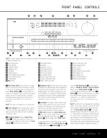
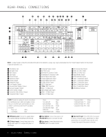
AVR 240 ˜ˆ ı DIGITAL PRO LOGIC 3 STEREO HEADPHONE LOGIC 7 DSP 5 7 CH. STEREO SURR. OFF FRONT-PANEL CONTROLS Ù ÛÚ Ò VID 1 DVD VID 2 CD VID 3 FMAM VID 4 TAPE 6 8 CH Optical 4 Coaxial 4 Video 4 13 2 57 4 6 8 9 !# % & ( Ô ) @)$ ^ * Ó NOTE: To make it easier to follow the instructions that refer to this illustration, a larger copy may be downloaded from the Product Support section for this product at www.harmankardon.com. 1 Main Power Switch 2 Power Indicator 3 Standby/On Switch 4 Headphone Jack 5 Tone Mode 6 Speaker Selector 7 Surround Mode Group Selector 8 Surround Mode Selector 9 Tuning Selector ) ‹/› Buttons ! Tuner Band Selector @ Set Button # Digital Input Selector $ Preset Station Selector % Delay Adjust Selector ^ Input Source Selector & Tuner Mode Selector * Optical 3 Digital Audio Input ( Coaxial 3 Digital Audio Input Ó Video 4 Video Input Jacks Ô Video 4 Audio Input Jacks Channel Adjust Selector Ò Volume Control Ú Input Indicators Û Speaker/Channel Input Indicators Ù Upper Display Line ı Lower Display Line ˆ Surround Mode Indicators ˜ Remote Sensor Window 1 Main Power Switch: Press this button to apply power to the AVR 240. When the switch is pressed in, the unit is in a Standby mode, as indicated by the amber Power Indicator 2. This button MUST be pressed in to operate the unit. To turn the unit off and prevent the use of the remote control, this switch should be pressed until it pops out from the front panel and the word "OFF" is seen at the top of the switch. NOTE: This switch is normally left in the "ON" position. 2 Power Indicator: This LED lights amber when the unit is in the Standby mode to signal that the AVR is ready to be turned on. When the unit is in operation, the indicator is blue. 3 Standby/On Switch: When the Main Power Switch 1 is "ON," press this button to turn on the AVR 240; press it again to turn the unit off. The Power Indicator 2 turns blue when the unit is on. 4 Headphone Jack: This jack may be used to listen to the AVR 240's output through a pair of headphones. The speakers will automatically be turned off when the headphone jack is in use. When configuring your system using EzSet+, the calibration microphone should be plugged into this jack using the supplied adaptor that converts the small mini-plug at the end of the microphone's cord to a 1/4" plug. 5 Tone Mode: This button controls the tone mode settings, enabling adjustment of the bass and treble boost/cut. You may also use it to take the tone controls out of the signal path completely for "flat" response. The first press of the button displays a TONE IN message in the Lower Display Line ı and in the on-screen display. To take the controls out of the signal path, press either of the ‹/› Buttons ) until the display reads TONE OUT. To change the bass or treble settings, make sure that TONE IN appears in the Lower Display Line ı or press either of the ‹/› Buttons ) until it does. Press the Tone Mode Button 5 until the desired option of TREBLE MODE or BASS MODE appears in the Lower Display Line ı and in the on-screen display and then press either of the ‹/› Buttons ) to enter the desired boost or cut setting. Both treble and bass contours may be boosted or cut by up to + or -10dB in increments of 2dB. See pages 22 and 32 for more information on the tone controls. NOTE: The AVR 240 is not equipped with a traditional Balance control. When listening to two-channel materials, if you wish to adjust the stereo image, you may use the Channel Adjust Selector to increase or decrease the level of the left front channel by up to + or -10dB, and then to decrease or increase the right front channel by the corresponding amount. However, when listening to surround materials and most twochannel materials, it is recommended that you leave these settings at the results obtained during the configuration process described on pages 20 through 31. FRONT-PANEL CONTROLS 5
-
 1
1 -
 2
2 -
 3
3 -
 4
4 -
 5
5 -
 6
6 -
 7
7 -
 8
8 -
 9
9 -
 10
10 -
 11
11 -
12
-
13
-
14
-
15
-
16
-
17
-
18
-
19
-
20
-
21
-
22
-
23
-
24
-
25
-
26
-
27
-
28
-
29
-
30
-
31
-
32
-
33
-
34
-
35
-
36
-
37
-
38
-
39
-
40
-
41
-
42
-
43
-
44
-
45
-
46
-
47
-
48
-
49
-
50
-
51
-
52
-
53
-
54
-
55
-
56
-
57
-
58
-
59
-
60
-
61
-
62
-
63
-
64
 |
 |
