HP 1050c Service Manual - Page 212
Refer to Remove the Printhead Cleaners Refer to the User Guide., Electronics Module Left - designjet 1055cm user guide
 |
View all HP 1050c manuals
Add to My Manuals
Save this manual to your list of manuals |
Page 212 highlights
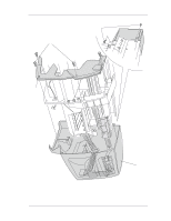
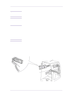
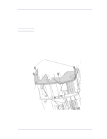
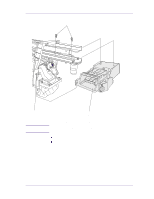
Removal and Installation Right Hand Cover Refer to Figure 1 NOTE Removal 1. Remove the Printhead Cleaners (Refer to the User Guide). Make sure that the Service Station Carriage is pushed to the back before trying to remove the Right Cover. WARNING NOTE NOTE Switch off the printer and remove the power cable. 1. Remove the following: 1. "Electronics Module Left Rear Cover" see page 8-24. Make sure you take care when removing the ferrite which is attached to the sideplate with a cable tie. 2. Disconnect the front panel cable from position P16 FRONT PANEL on the electronics module. 3. Disconnect the aerosol fan cable from position P7 AEROSOL FAN on the electronics module. 4. Remove two T-15 screws (item 1) from the right hand trim (item 2). Be careful not to drop the cover (item 3) once the securing fasteners have been removed. Support the cover throughout the next step. 5. Remove two T-15 screws (item 4) from the rear of the right hand cover which are securing the cover to the right hand side chassis. 6. Remove the right hand cover (item 3) by making sure you: a carefully pull the front panel cable and the aerosol fan cable from a hole in the right hand side chassis. b disconnect the service station door sensor cable, which hangs down from the service station cable. 8-4 HP DesignJets 1050C and 1055CM Printers Service Manual
-
 1
1 -
2
-
3
-
4
-
5
-
6
-
7
-
8
-
9
-
10
-
11
-
12
-
13
-
14
-
15
-
16
-
17
-
18
-
19
-
20
-
21
-
22
-
23
-
24
-
25
-
26
-
27
-
28
-
29
-
30
-
31
-
32
-
33
-
34
-
35
-
36
-
37
-
38
-
39
-
40
-
41
-
42
-
43
-
44
-
45
-
46
-
47
-
48
-
49
-
50
-
51
-
52
-
53
-
54
-
55
-
56
-
57
-
58
-
59
-
60
-
61
-
62
-
63
-
64
-
65
-
66
-
67
-
68
-
69
-
70
-
71
-
72
-
73
-
74
-
75
-
76
-
77
-
78
-
79
-
80
-
81
-
82
-
83
-
84
-
85
-
86
-
87
-
88
-
89
-
90
-
91
-
92
-
93
-
94
-
95
-
96
-
97
-
98
-
99
-
100
-
101
-
102
-
103
-
104
-
105
-
106
-
107
-
108
-
109
-
110
-
111
-
112
-
113
-
114
-
115
-
116
-
117
-
118
-
119
-
120
-
121
-
122
-
123
-
124
-
125
-
126
-
127
-
128
-
129
-
130
-
131
-
132
-
133
-
134
-
135
-
136
-
137
-
138
-
139
-
140
-
141
-
142
-
143
-
144
-
145
-
146
-
147
-
148
-
149
-
150
-
151
-
152
-
153
-
154
-
155
-
156
-
157
-
158
-
159
-
160
-
161
-
162
-
163
-
164
-
165
-
166
-
167
-
168
-
169
-
170
-
171
-
172
-
173
-
174
-
175
-
176
-
177
-
178
-
179
-
180
-
181
-
182
-
183
-
184
-
185
-
186
-
187
-
188
-
189
-
190
-
191
-
192
-
193
-
194
-
195
-
196
-
197
-
198
-
199
-
200
-
201
-
202
-
203
-
204
-
205
-
206
-
 207
207 -
 208
208 -
 209
209 -
 210
210 -
 211
211 -
 212
212 -
 213
213 -
 214
214 -
 215
215 -
 216
216 -
 217
217 -
218
-
219
-
220
-
221
-
222
-
223
-
224
-
225
-
226
-
227
-
228
-
229
-
230
-
231
-
232
-
233
-
234
-
235
-
236
-
237
-
238
-
239
-
240
-
241
-
242
-
243
-
244
-
245
-
246
-
247
-
248
-
249
-
250
-
251
-
252
-
253
-
254
-
255
-
256
-
257
-
258
-
259
-
260
-
261
-
262
-
263
-
264
-
265
-
266
-
267
-
268
-
269
-
270
-
271
-
272
-
273
-
274
-
275
-
276
-
277
-
278
-
279
-
280
-
281
-
282
-
283
-
284
-
285
-
286
-
287
-
288
-
289
-
290
-
291
-
292
-
293
-
294
-
295
-
296
-
297
-
298
-
299
-
300
-
301
-
302
-
303
-
304
-
305
-
306
-
307
-
308
-
309
-
310
-
311
-
312
-
313
-
314
-
315
-
316
-
317
-
318
-
319
-
320
-
321
-
322
 |
 |
