HP 1050c Service Manual - Page 260
Belt Installation
 |
View all HP 1050c manuals
Add to My Manuals
Save this manual to your list of manuals |
Page 260 highlights
Removal and Installation 3. When installing the belt, make sure it is not twisted and is installed in the correct orientation as shown in Figure 51. Installed in the direction of the Scan-Axis Motor NOTE Installed in the direction of the Tensioner Assembly Figure 51: Belt Installation C607442 You must perform the following Service Calibrations after the installation of the Carriage Assembly. n Carriage Height Calibration ⇒ Page 5-24. n Line Sensor ⇒ Page 5-9. n Service Station ⇒ Page 5-11. n Roller Mark Position ⇒ Page 5-13. n Color to Color Calibration ⇒ Page 5-16. n Pen Alignment ⇒ Page 5-22. 8-52 HP DesignJets 1050C and 1055CM Printers Service Manual
-
 1
1 -
2
-
3
-
4
-
5
-
6
-
7
-
8
-
9
-
10
-
11
-
12
-
13
-
14
-
15
-
16
-
17
-
18
-
19
-
20
-
21
-
22
-
23
-
24
-
25
-
26
-
27
-
28
-
29
-
30
-
31
-
32
-
33
-
34
-
35
-
36
-
37
-
38
-
39
-
40
-
41
-
42
-
43
-
44
-
45
-
46
-
47
-
48
-
49
-
50
-
51
-
52
-
53
-
54
-
55
-
56
-
57
-
58
-
59
-
60
-
61
-
62
-
63
-
64
-
65
-
66
-
67
-
68
-
69
-
70
-
71
-
72
-
73
-
74
-
75
-
76
-
77
-
78
-
79
-
80
-
81
-
82
-
83
-
84
-
85
-
86
-
87
-
88
-
89
-
90
-
91
-
92
-
93
-
94
-
95
-
96
-
97
-
98
-
99
-
100
-
101
-
102
-
103
-
104
-
105
-
106
-
107
-
108
-
109
-
110
-
111
-
112
-
113
-
114
-
115
-
116
-
117
-
118
-
119
-
120
-
121
-
122
-
123
-
124
-
125
-
126
-
127
-
128
-
129
-
130
-
131
-
132
-
133
-
134
-
135
-
136
-
137
-
138
-
139
-
140
-
141
-
142
-
143
-
144
-
145
-
146
-
147
-
148
-
149
-
150
-
151
-
152
-
153
-
154
-
155
-
156
-
157
-
158
-
159
-
160
-
161
-
162
-
163
-
164
-
165
-
166
-
167
-
168
-
169
-
170
-
171
-
172
-
173
-
174
-
175
-
176
-
177
-
178
-
179
-
180
-
181
-
182
-
183
-
184
-
185
-
186
-
187
-
188
-
189
-
190
-
191
-
192
-
193
-
194
-
195
-
196
-
197
-
198
-
199
-
200
-
201
-
202
-
203
-
204
-
205
-
206
-
207
-
208
-
209
-
210
-
211
-
212
-
213
-
214
-
215
-
216
-
217
-
218
-
219
-
220
-
221
-
222
-
223
-
224
-
225
-
226
-
227
-
228
-
229
-
230
-
231
-
232
-
233
-
234
-
235
-
236
-
237
-
238
-
239
-
240
-
241
-
242
-
243
-
244
-
245
-
246
-
247
-
248
-
249
-
250
-
251
-
252
-
253
-
254
-
 255
255 -
 256
256 -
 257
257 -
 258
258 -
 259
259 -
 260
260 -
 261
261 -
 262
262 -
 263
263 -
 264
264 -
 265
265 -
266
-
267
-
268
-
269
-
270
-
271
-
272
-
273
-
274
-
275
-
276
-
277
-
278
-
279
-
280
-
281
-
282
-
283
-
284
-
285
-
286
-
287
-
288
-
289
-
290
-
291
-
292
-
293
-
294
-
295
-
296
-
297
-
298
-
299
-
300
-
301
-
302
-
303
-
304
-
305
-
306
-
307
-
308
-
309
-
310
-
311
-
312
-
313
-
314
-
315
-
316
-
317
-
318
-
319
-
320
-
321
-
322
 |
 |

Removal and Installation
8-52
HP DesignJets 1050C and 1055CM Printers Service Manual
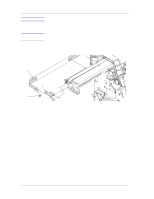
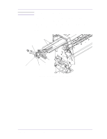
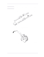
3.
When installing the belt, make sure it is not twisted and is installed
in the correct orientation as shown in Figure 51.
Figure 51: Belt Installation
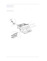
NOTE
You must perform the following Service Calibrations after the
installation of the Carriage Assembly.
Carriage Height Calibration
⇒
Page
5-24
.
Line Sensor
⇒
Page
5-9
.
Service Station
⇒
Page
5-11
.
Roller Mark Position
⇒
Page
5-13
.
Color to Color Calibration
⇒
Page
5-16
.
Pen Alignment
⇒
Page
5-22
.
Installed in the direction
of the Scan-Axis Motor
Installed in the direction
of the Tensioner Assembly
C607442