HP 14-bs000 Maintenance and Service Guide - Page 71
Power button board cable, Display cable
 |
View all HP 14-bs000 manuals
Add to My Manuals
Save this manual to your list of manuals |
Page 71 highlights
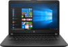
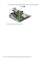
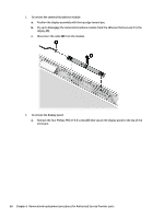
3. Disconnect the power from the computer by first unplugging the power cord from the AC outlet and then unplugging the AC adapter from the computer. 4. Remove the battery (see Battery on page 32). 5. Remove the optical drive (see Optical drive on page 34), if installed. 6. Remove the bottom cover (see Bottom cover on page 41). 7. Remove the WLAN module (see WLAN module on page 43). 8. Remove the memory module (see Memory module on page 45). 9. Remove the solid-state drive (see Solid-state drive (SSD) on page 51). To remove the system board: 1. Position the computer upright, and then disconnect the following cables from the system board: (1): USB board cable (2): Display cable (3): Power connector cable (4): Power button board cable (5): TouchPad cable (6): TouchPad button board cable (7): Keyboard cable 2. Remove the three Phillips PM2.5×3.5 screws (1) that secure the system board to the computer. Component replacement procedures 63
-
 1
1 -
2
-
3
-
4
-
5
-
6
-
7
-
8
-
9
-
10
-
11
-
12
-
13
-
14
-
15
-
16
-
17
-
18
-
19
-
20
-
21
-
22
-
23
-
24
-
25
-
26
-
27
-
28
-
29
-
30
-
31
-
32
-
33
-
34
-
35
-
36
-
37
-
38
-
39
-
40
-
41
-
42
-
43
-
44
-
45
-
46
-
47
-
48
-
49
-
50
-
51
-
52
-
53
-
54
-
55
-
56
-
57
-
58
-
59
-
60
-
61
-
62
-
63
-
64
-
65
-
 66
66 -
 67
67 -
 68
68 -
 69
69 -
 70
70 -
 71
71 -
 72
72 -
 73
73 -
 74
74 -
 75
75 -
 76
76 -
77
-
78
-
79
-
80
-
81
-
82
-
83
-
84
-
85
-
86
-
87
-
88
-
89
-
90
-
91
-
92
-
93
-
94
-
95
-
96
-
97
-
98
-
99
-
100
-
101
-
102
-
103
-
104
-
105
-
106
-
107
-
108
-
109
-
110
-
111
-
112
 |
 |