HP 14-bs000 Maintenance and Service Guide - Page 81
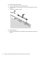
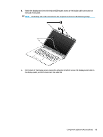
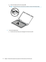
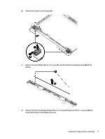
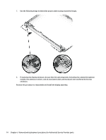
Component replacement procedures, and then remove the cable from the display enclosure
 |
View all HP 14-bs000 manuals
Add to My Manuals
Save this manual to your list of manuals |
Page 81 highlights
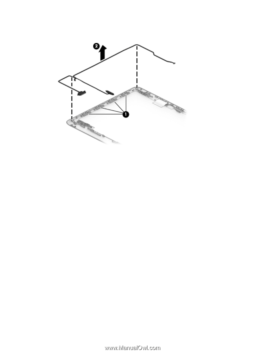
6. To remove the display/camera cable, remove the cable from the clips built into the side of the display enclosure (1), and then remove the cable from the display enclosure (2). Component replacement procedures 73
-
 1
1 -
2
-
3
-
4
-
5
-
6
-
7
-
8
-
9
-
10
-
11
-
12
-
13
-
14
-
15
-
16
-
17
-
18
-
19
-
20
-
21
-
22
-
23
-
24
-
25
-
26
-
27
-
28
-
29
-
30
-
31
-
32
-
33
-
34
-
35
-
36
-
37
-
38
-
39
-
40
-
41
-
42
-
43
-
44
-
45
-
46
-
47
-
48
-
49
-
50
-
51
-
52
-
53
-
54
-
55
-
56
-
57
-
58
-
59
-
60
-
61
-
62
-
63
-
64
-
65
-
66
-
67
-
68
-
69
-
70
-
71
-
72
-
73
-
74
-
75
-
 76
76 -
 77
77 -
 78
78 -
 79
79 -
 80
80 -
 81
81 -
 82
82 -
 83
83 -
 84
84 -
 85
85 -
 86
86 -
87
-
88
-
89
-
90
-
91
-
92
-
93
-
94
-
95
-
96
-
97
-
98
-
99
-
100
-
101
-
102
-
103
-
104
-
105
-
106
-
107
-
108
-
109
-
110
-
111
-
112
 |
 |
6.
To remove the display/camera cable, remove the cable from the clips built into the side of the display
enclosure
(1)
, and then remove the cable from the display enclosure
(2)
.
Component replacement procedures
73