HP 14-bs000 Maintenance and Service Guide - Page 75
be careful not to peel the, display bezel until the bezel disengages from the display enclosure.
 |
View all HP 14-bs000 manuals
Add to My Manuals
Save this manual to your list of manuals |
Page 75 highlights
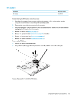
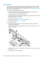
5. Separate the display from the computer (3). If it is necessary to replace any of the display assembly subcomponents: 1. To remove the display bezel: a. Flex the inside of the top edge (1), the left and right edges (2), and the bottom edge (3) of the display bezel until the bezel disengages from the display enclosure. NOTE: When removing the bezel from the bottom of the display (3), be careful not to peel the Mylar from the bottom of the display panel. b. Remove the display bezel (4). NOTE: The display will not be connected to the computer as shown in the following image. Component replacement procedures 67
-
 1
1 -
2
-
3
-
4
-
5
-
6
-
7
-
8
-
9
-
10
-
11
-
12
-
13
-
14
-
15
-
16
-
17
-
18
-
19
-
20
-
21
-
22
-
23
-
24
-
25
-
26
-
27
-
28
-
29
-
30
-
31
-
32
-
33
-
34
-
35
-
36
-
37
-
38
-
39
-
40
-
41
-
42
-
43
-
44
-
45
-
46
-
47
-
48
-
49
-
50
-
51
-
52
-
53
-
54
-
55
-
56
-
57
-
58
-
59
-
60
-
61
-
62
-
63
-
64
-
65
-
66
-
67
-
68
-
69
-
 70
70 -
 71
71 -
 72
72 -
 73
73 -
 74
74 -
 75
75 -
 76
76 -
 77
77 -
 78
78 -
 79
79 -
 80
80 -
81
-
82
-
83
-
84
-
85
-
86
-
87
-
88
-
89
-
90
-
91
-
92
-
93
-
94
-
95
-
96
-
97
-
98
-
99
-
100
-
101
-
102
-
103
-
104
-
105
-
106
-
107
-
108
-
109
-
110
-
111
-
112
 |
 |
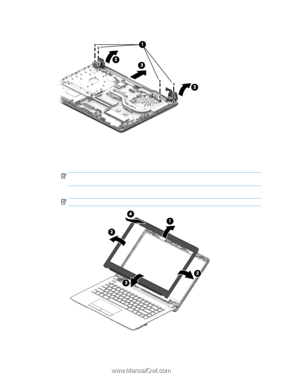
5.
Separate the display from the computer
(3)
.
If it is necessary to replace any of the display assembly subcomponents:
1.
To remove the display bezel:
a.
Flex the inside of the top edge
(1)
, the left and right edges
(2)
, and the bottom edge
(3)
of the
display bezel until the bezel disengages from the display enclosure.
NOTE:
When removing the bezel from the bottom of the display
(3)
, be careful not to peel the
Mylar from the bottom of the display panel.
b.
Remove the display bezel
(4)
.
NOTE:
The display will not be connected to the computer as shown in the following image.
Component replacement procedures
67