HP 14.4kVA HP Monitored Power Distribution Unit User Guide - Page 25
Connecting Two PDUs in a Daisy Chain, Connecting the PDU to a LAN
 |
View all HP 14.4kVA manuals
Add to My Manuals
Save this manual to your list of manuals |
Page 25 highlights
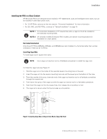
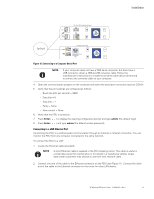
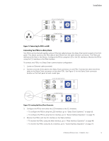
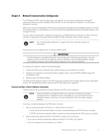
22U, 36U, 42U Model Front Panel Installation 1U Model Front Panel Figure 11. Connecting the PDU to a LAN Connecting Two PDUs in a Daisy Chain Two PDUs can be chained together using an Ethernet cable between the Daisy Chain ports located on the front panel. This allows access to the PDU data of both PDUs from the same network connection. The PDUs are defined as the Host or the Device. Configure the PDUs using the LCD or the CLI interfaces. Monitor the PDUs using the CLI interface or the Web interface. To connect two PDUs in a Daisy Chain communication configuration: 1. Locate an Ethernet cable (provided). 2. Connect one end of the cable to the Daisy Chain connector on one PDU. Connect the other end of the cable to the Daisy Chain connector on the other PDU. See Figure 12 for the Daisy Chain connector location on the front panel of each model type. 22U, 36U, 42U Model Front Panel 1U Model Front Panel Figure 12. Locating the Daisy Chain Connector 3. Configure the PDUs with either the LCD interface or the CLI interface. l To configure the PDUs using the LCD interface, go to "Daisy Chain Submenu" on page 43. l To configure the PDUs using the CLI interface, go to "Serial Interface Operation" on page 73. 4. Monitor the PDUs with the CLI interface or the Web interface. l To monitor the PDUs using the Web interface, go to "Web Interface Operation" on page 48. l To monitor the PDUs using the CLI interface, go to "Serial Interface Operation" on page 73. HP Monitored PDU User's Guide P-164000281-Rev 1 19
-
 1
1 -
2
-
3
-
4
-
5
-
6
-
7
-
8
-
9
-
10
-
11
-
12
-
13
-
14
-
15
-
16
-
17
-
18
-
19
-
 20
20 -
 21
21 -
 22
22 -
 23
23 -
 24
24 -
 25
25 -
 26
26 -
 27
27 -
 28
28 -
 29
29 -
 30
30 -
31
-
32
-
33
-
34
-
35
-
36
-
37
-
38
-
39
-
40
-
41
-
42
-
43
-
44
-
45
-
46
-
47
-
48
-
49
-
50
-
51
-
52
-
53
-
54
-
55
-
56
-
57
-
58
-
59
-
60
-
61
-
62
-
63
-
64
-
65
-
66
-
67
-
68
-
69
-
70
-
71
-
72
-
73
-
74
-
75
-
76
-
77
-
78
-
79
-
80
-
81
-
82
-
83
-
84
-
85
-
86
-
87
-
88
-
89
-
90
-
91
-
92
-
93
-
94
-
95
-
96
-
97
-
98
-
99
-
100
-
101
-
102
-
103
-
104
-
105
-
106
-
107
-
108
-
109
-
110
-
111
-
112
-
113
-
114
-
115
-
116
-
117
-
118
-
119
-
120
 |
 |
