HP 240 HP 450 Notebook PC and HP 455 Notebook PC Maintenance and Service Guide - Page 100
Fan/heat sink assembly, Hard drive see - software
 |
View all HP 240 manuals
Add to My Manuals
Save this manual to your list of manuals |
Page 100 highlights
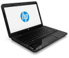
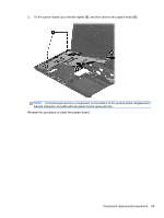
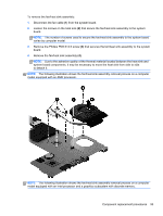
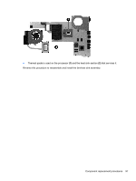
Fan/heat sink assembly NOTE: The fan/heat sink assembly spare part kit includes replacement thermal materials. Description Spare part number Fan/heat sink assembly for use only with computer models equipped with an AMD processor 688281-001 Fan/heat sink assembly for use only with computer models equipped with an Intel processor and a 685087-001 graphics subsystem with discrete video memory Fan/heat sink assembly for use only with computer models equipped with an Intel processor and a 685086-001 graphics subsystem with UMA video memory NOTE: To properly ventilate the computer, allow at least 7.6 cm (3.0 in) of clearance on the left side of the computer. The computer uses an electric fan for ventilation. The fan is controlled by a temperature sensor and is designed to turn on automatically when high temperature conditions exist. These conditions are affected by high external temperatures, system power consumption, power management/battery conservation configurations, battery fast charging, and software requirements. Exhaust air is displaced through the ventilation grill located on the left side of the computer. Before removing the fan/heat sink assembly, follow these steps: 1. Shut down the computer. If you are unsure whether the computer is off or in Hibernation, turn the computer on, and then shut it down through the operating system. 2. Disconnect all external devices connected to the computer. 3. Disconnect the power from the computer by first unplugging the power cord from the AC outlet and then unplugging the AC adapter from the computer. 4. Remove the battery (see Battery on page 41), and then remove the following components: ● WLAN module (see WLAN module on page 49) ● Hard drive (see Hard drive on page 54) ● Keyboard (see Keyboard on page 60) ● Top cover (see Top cover on page 63) ● Speakers (see Speakers on page 71) ● USB board (see USB board on page 73) ● Power connector cable (see Power connector cable on page 75) ● Display assembly (see Display assembly on page 77) ● System board (see System board on page 86) 92 Chapter 4 Removal and replacement procedures
-
 1
1 -
2
-
3
-
4
-
5
-
6
-
7
-
8
-
9
-
10
-
11
-
12
-
13
-
14
-
15
-
16
-
17
-
18
-
19
-
20
-
21
-
22
-
23
-
24
-
25
-
26
-
27
-
28
-
29
-
30
-
31
-
32
-
33
-
34
-
35
-
36
-
37
-
38
-
39
-
40
-
41
-
42
-
43
-
44
-
45
-
46
-
47
-
48
-
49
-
50
-
51
-
52
-
53
-
54
-
55
-
56
-
57
-
58
-
59
-
60
-
61
-
62
-
63
-
64
-
65
-
66
-
67
-
68
-
69
-
70
-
71
-
72
-
73
-
74
-
75
-
76
-
77
-
78
-
79
-
80
-
81
-
82
-
83
-
84
-
85
-
86
-
87
-
88
-
89
-
90
-
91
-
92
-
93
-
94
-
 95
95 -
 96
96 -
 97
97 -
 98
98 -
 99
99 -
 100
100 -
 101
101 -
 102
102 -
 103
103 -
 104
104 -
 105
105 -
106
-
107
-
108
-
109
-
110
-
111
-
112
-
113
-
114
-
115
-
116
-
117
-
118
-
119
-
120
-
121
-
122
-
123
-
124
-
125
-
126
-
127
-
128
-
129
-
130
-
131
-
132
-
133
-
134
-
135
-
136
-
137
-
138
-
139
-
140
-
141
-
142
 |
 |