HP 240 HP 450 Notebook PC and HP 455 Notebook PC Maintenance and Service Guide - Page 96
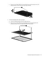
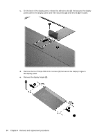
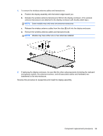
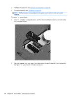
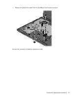
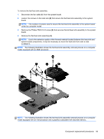
Turn the computer back over, open it, and then remove the two Phillips PM2.5×4.0 screws
 |
View all HP 240 manuals
Add to My Manuals
Save this manual to your list of manuals |
Page 96 highlights
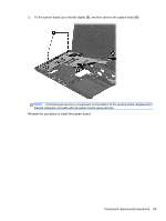
● Fan/heat sink assembly (see Fan/heat sink assembly on page 92) ● Processor (Intel only; see Processor on page 98) NOTE: AMD processors come soldered to the system board and cannot be removed or replaced. To remove the system board: 1. Close the computer, turn it upside down, and then disconnect the optical drive connector cable from the system board. 2. Turn the computer back over, open it, and then remove the two Phillips PM2.5×4.0 screws (1) that secure the system board to the base enclosure. 88 Chapter 4 Removal and replacement procedures
-
 1
1 -
2
-
3
-
4
-
5
-
6
-
7
-
8
-
9
-
10
-
11
-
12
-
13
-
14
-
15
-
16
-
17
-
18
-
19
-
20
-
21
-
22
-
23
-
24
-
25
-
26
-
27
-
28
-
29
-
30
-
31
-
32
-
33
-
34
-
35
-
36
-
37
-
38
-
39
-
40
-
41
-
42
-
43
-
44
-
45
-
46
-
47
-
48
-
49
-
50
-
51
-
52
-
53
-
54
-
55
-
56
-
57
-
58
-
59
-
60
-
61
-
62
-
63
-
64
-
65
-
66
-
67
-
68
-
69
-
70
-
71
-
72
-
73
-
74
-
75
-
76
-
77
-
78
-
79
-
80
-
81
-
82
-
83
-
84
-
85
-
86
-
87
-
88
-
89
-
90
-
 91
91 -
 92
92 -
 93
93 -
 94
94 -
 95
95 -
 96
96 -
 97
97 -
 98
98 -
 99
99 -
 100
100 -
 101
101 -
102
-
103
-
104
-
105
-
106
-
107
-
108
-
109
-
110
-
111
-
112
-
113
-
114
-
115
-
116
-
117
-
118
-
119
-
120
-
121
-
122
-
123
-
124
-
125
-
126
-
127
-
128
-
129
-
130
-
131
-
132
-
133
-
134
-
135
-
136
-
137
-
138
-
139
-
140
-
141
-
142
 |
 |

●
Fan/heat sink assembly (see
Fan/heat sink assembly
on page
92
)
●
Processor (Intel only; see
Processor
on page
98
)
NOTE:
AMD processors come soldered to the system board and cannot be removed or
replaced.
To remove the system board:
1.
Close the computer, turn it upside down, and then disconnect the optical drive connector cable
from the system board.
2.
Turn the computer back over, open it, and then remove the two Phillips PM2.5×4.0 screws
(1)
that secure the system board to the base enclosure.
88
Chapter 4
Removal and replacement procedures