HP 240 HP 450 Notebook PC and HP 455 Notebook PC Maintenance and Service Guide - Page 73
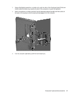
until the left and right sides disengage from the, base enclosure.
 |
View all HP 240 manuals
Add to My Manuals
Save this manual to your list of manuals |
Page 73 highlights
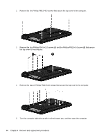
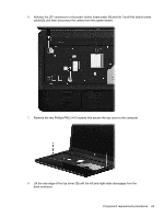
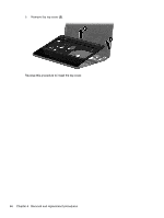
6. Release the ZIF connectors to the power button board cable (1) and the TouchPad button board cable (2), and then disconnect the cables from the system board. 7. Remove the two Phillips PM2.5×6.0 screws that secure the top cover to the computer. 8. Lift the rear edge of the top cover (1) until the left and right sides disengage from the base enclosure. Component replacement procedures 65
-
 1
1 -
2
-
3
-
4
-
5
-
6
-
7
-
8
-
9
-
10
-
11
-
12
-
13
-
14
-
15
-
16
-
17
-
18
-
19
-
20
-
21
-
22
-
23
-
24
-
25
-
26
-
27
-
28
-
29
-
30
-
31
-
32
-
33
-
34
-
35
-
36
-
37
-
38
-
39
-
40
-
41
-
42
-
43
-
44
-
45
-
46
-
47
-
48
-
49
-
50
-
51
-
52
-
53
-
54
-
55
-
56
-
57
-
58
-
59
-
60
-
61
-
62
-
63
-
64
-
65
-
66
-
67
-
 68
68 -
 69
69 -
 70
70 -
 71
71 -
 72
72 -
 73
73 -
 74
74 -
 75
75 -
 76
76 -
 77
77 -
 78
78 -
79
-
80
-
81
-
82
-
83
-
84
-
85
-
86
-
87
-
88
-
89
-
90
-
91
-
92
-
93
-
94
-
95
-
96
-
97
-
98
-
99
-
100
-
101
-
102
-
103
-
104
-
105
-
106
-
107
-
108
-
109
-
110
-
111
-
112
-
113
-
114
-
115
-
116
-
117
-
118
-
119
-
120
-
121
-
122
-
123
-
124
-
125
-
126
-
127
-
128
-
129
-
130
-
131
-
132
-
133
-
134
-
135
-
136
-
137
-
138
-
139
-
140
-
141
-
142
 |
 |
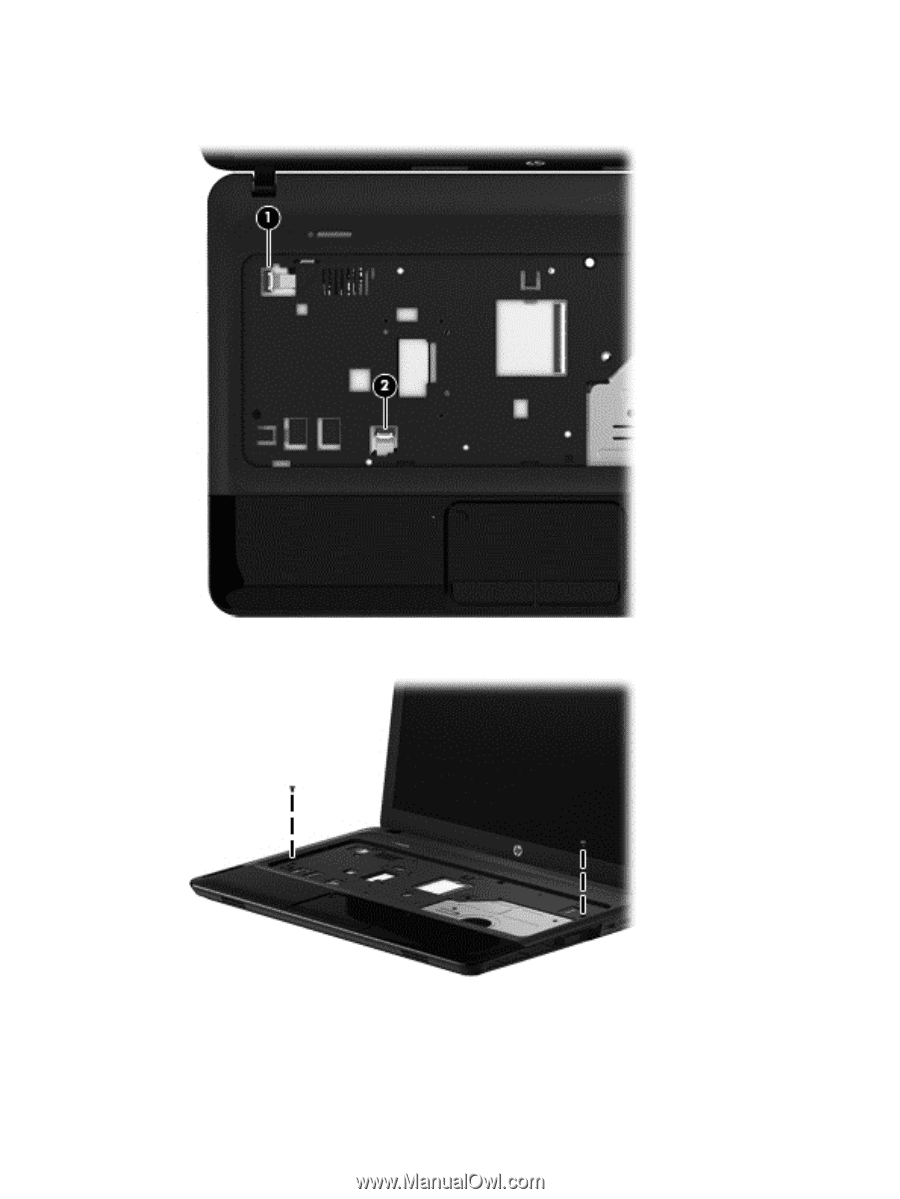
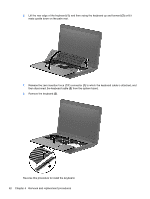
6.
Release the ZIF connectors to the power button board cable
(1)
and the TouchPad button board
cable
(2)
, and then disconnect the cables from the system board.
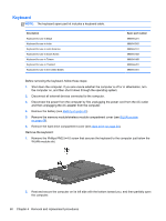
7.
Remove the two Phillips PM2.5×6.0 screws that secure the top cover to the computer.
8.
Lift the rear edge of the top cover
(1)
until the left and right sides disengage from the
base enclosure.
Component replacement procedures
65