HP 240 HP 450 Notebook PC and HP 455 Notebook PC Maintenance and Service Guide - Page 87
Flex the inside edges of the top edge, the display bezel spare part kit.
 |
View all HP 240 manuals
Add to My Manuals
Save this manual to your list of manuals |
Page 87 highlights
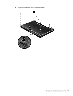
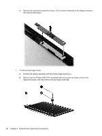
4. Remove the display assembly (2). NOTE: Models may have either one or two antennas installed. If it is necessary to replace any of the display assembly subcomponents: 1. To remove the display bezel: a. Remove the two Mylar screw covers (1) and the two Phillips PM2.5×4.0 screws (2) that secure the display bezel to the display assembly. The Mylar screw covers are included with the display bezel spare part kit. b. Flex the inside edges of the top edge (3), the left and right edges (4), and the bottom edge (5) of the display bezel until the bezel disengages from the display enclosure. Component replacement procedures 79
-
 1
1 -
2
-
3
-
4
-
5
-
6
-
7
-
8
-
9
-
10
-
11
-
12
-
13
-
14
-
15
-
16
-
17
-
18
-
19
-
20
-
21
-
22
-
23
-
24
-
25
-
26
-
27
-
28
-
29
-
30
-
31
-
32
-
33
-
34
-
35
-
36
-
37
-
38
-
39
-
40
-
41
-
42
-
43
-
44
-
45
-
46
-
47
-
48
-
49
-
50
-
51
-
52
-
53
-
54
-
55
-
56
-
57
-
58
-
59
-
60
-
61
-
62
-
63
-
64
-
65
-
66
-
67
-
68
-
69
-
70
-
71
-
72
-
73
-
74
-
75
-
76
-
77
-
78
-
79
-
80
-
81
-
 82
82 -
 83
83 -
 84
84 -
 85
85 -
 86
86 -
 87
87 -
 88
88 -
 89
89 -
 90
90 -
 91
91 -
 92
92 -
93
-
94
-
95
-
96
-
97
-
98
-
99
-
100
-
101
-
102
-
103
-
104
-
105
-
106
-
107
-
108
-
109
-
110
-
111
-
112
-
113
-
114
-
115
-
116
-
117
-
118
-
119
-
120
-
121
-
122
-
123
-
124
-
125
-
126
-
127
-
128
-
129
-
130
-
131
-
132
-
133
-
134
-
135
-
136
-
137
-
138
-
139
-
140
-
141
-
142
 |
 |
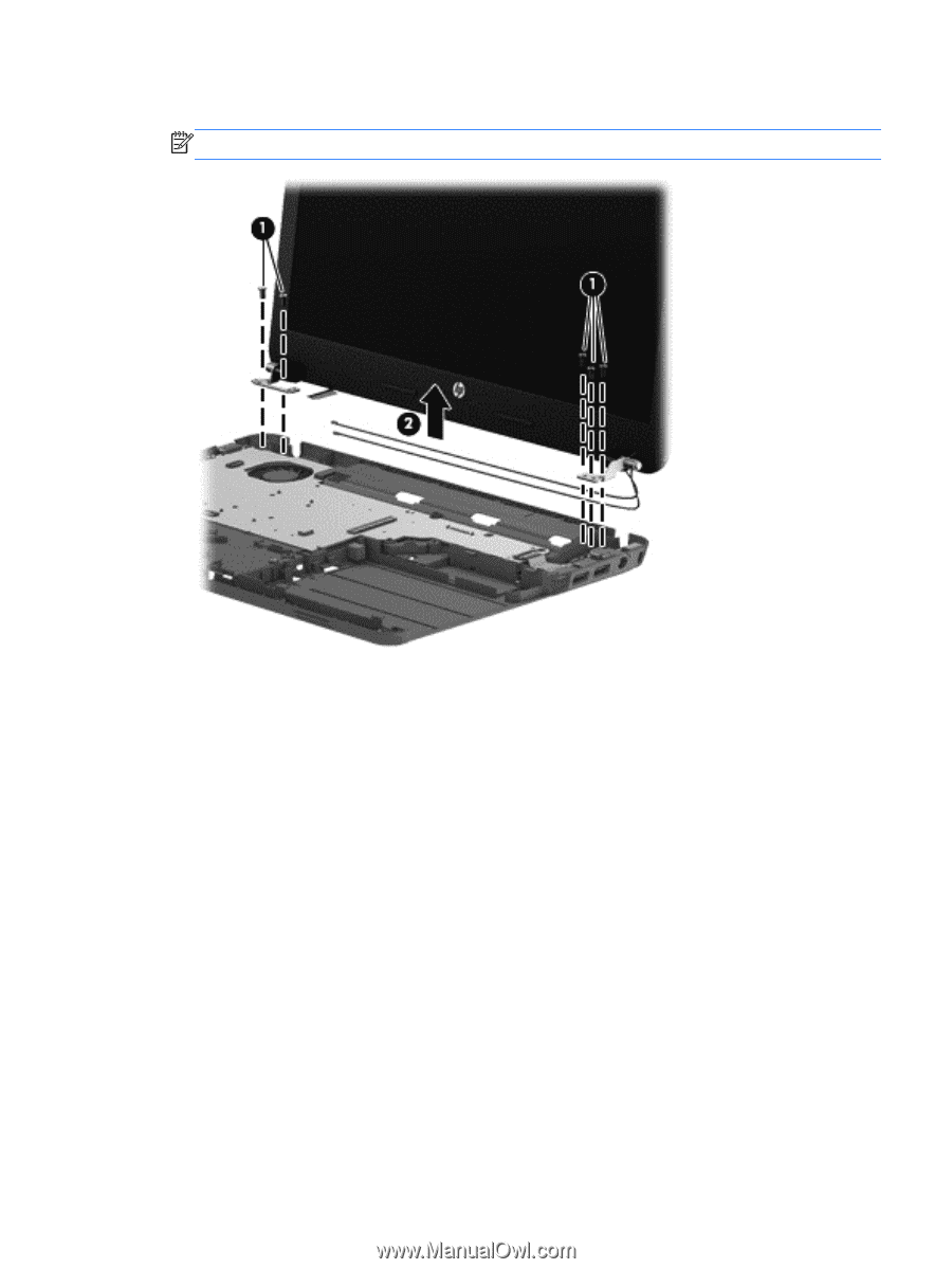
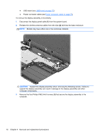
4.
Remove the display assembly
(2)
.
NOTE:
Models may have either one or two antennas installed.
If it is necessary to replace any of the display assembly subcomponents:
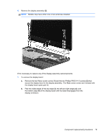
1.
To remove the display bezel:
a.
Remove the two Mylar screw covers
(1)
and the two Phillips PM2.5×4.0 screws
(2)
that
secure the display bezel to the display assembly. The Mylar screw covers are included with
the display bezel spare part kit.
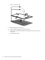
b.
Flex the inside edges of the top edge
(3)
, the left and right edges
(4)
, and
the bottom edge
(5)
of the display bezel until the bezel disengages from the
display enclosure.
Component replacement procedures
79