HP 240 HP 450 Notebook PC and HP 455 Notebook PC Maintenance and Service Guide - Page 101
system board components, it may be necessary to move the heat sink from side to side
 |
View all HP 240 manuals
Add to My Manuals
Save this manual to your list of manuals |
Page 101 highlights
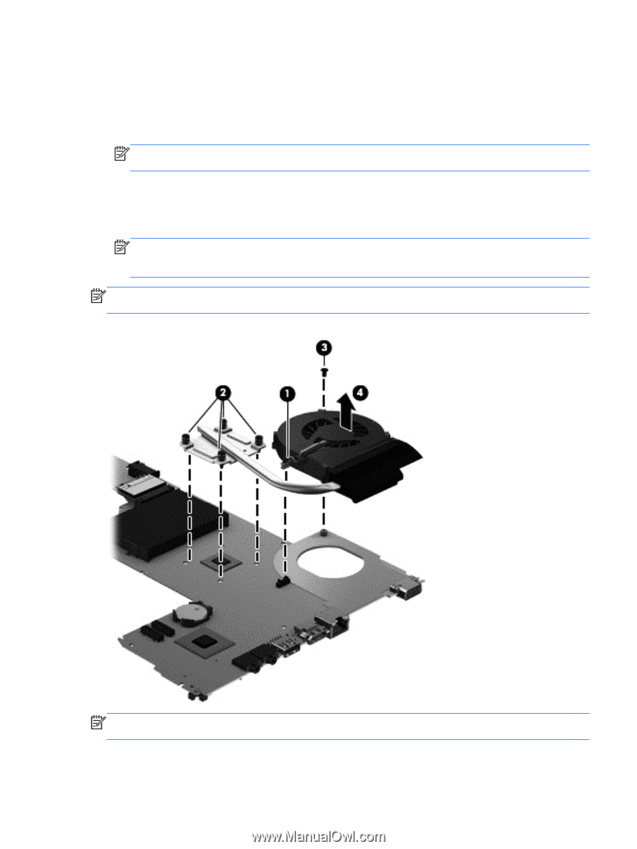
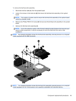
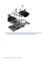
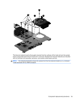
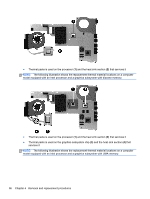
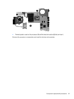
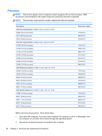
To remove the fan/heat sink assembly: 1. Disconnect the fan cable (1) from the system board. 2. Loosen the screws on the heat sink (2) that secure the fan/heat sink assembly to the system board. NOTE: The number of screws used to secure the fan/heat sink assembly to the system board varies by computer model. 3. Remove the Phillips PM2.0×3.0 screw (3) that secures the fan/heat sink assembly to the system board. 4. Remove the fan/heat sink assembly (4). NOTE: Due to the adhesive quality of the thermal material located between the heat sink and system board components, it may be necessary to move the heat sink from side to side to detach it. NOTE: The following illustration shows the fan/heat sink assembly removal process on a computer model equipped with an AMD processor. NOTE: The following illustration shows the fan/heat sink assembly removal process on a computer model equipped with an Intel processor and a graphics subsystem with discrete memory. Component replacement procedures 93
-
 1
1 -
2
-
3
-
4
-
5
-
6
-
7
-
8
-
9
-
10
-
11
-
12
-
13
-
14
-
15
-
16
-
17
-
18
-
19
-
20
-
21
-
22
-
23
-
24
-
25
-
26
-
27
-
28
-
29
-
30
-
31
-
32
-
33
-
34
-
35
-
36
-
37
-
38
-
39
-
40
-
41
-
42
-
43
-
44
-
45
-
46
-
47
-
48
-
49
-
50
-
51
-
52
-
53
-
54
-
55
-
56
-
57
-
58
-
59
-
60
-
61
-
62
-
63
-
64
-
65
-
66
-
67
-
68
-
69
-
70
-
71
-
72
-
73
-
74
-
75
-
76
-
77
-
78
-
79
-
80
-
81
-
82
-
83
-
84
-
85
-
86
-
87
-
88
-
89
-
90
-
91
-
92
-
93
-
94
-
95
-
 96
96 -
 97
97 -
 98
98 -
 99
99 -
 100
100 -
 101
101 -
 102
102 -
 103
103 -
 104
104 -
 105
105 -
 106
106 -
107
-
108
-
109
-
110
-
111
-
112
-
113
-
114
-
115
-
116
-
117
-
118
-
119
-
120
-
121
-
122
-
123
-
124
-
125
-
126
-
127
-
128
-
129
-
130
-
131
-
132
-
133
-
134
-
135
-
136
-
137
-
138
-
139
-
140
-
141
-
142
 |
 |