HP BladeSystem bc2800 Service Reference Guide: HP BladeSystem PC bc2000/bc2500 - Page 16
Passwords, Remove a Setup Password, Establish a Setup Password
 |
View all HP BladeSystem bc2800 manuals
Add to My Manuals
Save this manual to your list of manuals |
Page 16 highlights
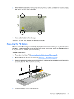
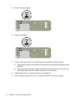
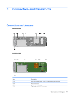
SW50 XBT1 XMM1 or DIMM1 XMM2 or DIMM2 XU1 CMOS reset button. RTC battery. Memory module socket 1. Memory module socket 2. Processor socket. Passwords Remove a Setup Password 1. Power down the blade PC (Powering Down the BladeSystem PC on page 3). 2. Remove the blade PC (Removing a Blade PC on page 4). 3. Remove a jumper on the E49 header. 4. Power up the unit. The password is removed. Establish a Setup Password The blade PC ships from the factory with the jumper installed on the E49 header. If the jumper is installed, you can establish a Setup Password by powering up the blade PC and using F10. If the jumper has been removed, use the following steps: 1. Power down the blade PC (Powering Down the BladeSystem PC on page 3). 2. Remove the blade PC (Removing a Blade PC on page 4). 3. Install the jumper from the E49 header. 4. Power up and use F10 Setup to establish the Setup Password. 12 Chapter 3 Connectors and Passwords
-
 1
1 -
2
-
3
-
4
-
5
-
6
-
7
-
8
-
9
-
10
-
 11
11 -
 12
12 -
 13
13 -
 14
14 -
 15
15 -
 16
16 -
 17
17 -
 18
18 -
 19
19 -
 20
20 -
 21
21 -
22
-
23
 |
 |
