HP Carrier-grade cc3300 UserÆs Guide and Technical UserÆs Gu - Page 96
Configuration Jumpers, System Recovery and Update Jumpers J1E1
 |
View all HP Carrier-grade cc3300 manuals
Add to My Manuals
Save this manual to your list of manuals |
Page 96 highlights
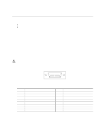
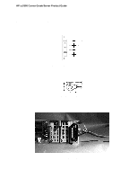
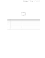
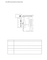
HP cc3300 Carrier Grade Server Product Guide Configuration Jumpers This section describes the jumper blocks that control various configuration options. Figure 36 shows the names and location of the configuration jumpers. The shaded areas show the default jumper placement for each configurable option. Table 17 describes the system recovery and update jumper options. J6A2 DSR to Pin #7 DCD to Pin #7 DSR DCD J1E1 A BMC WP B CMOS CLR C PSWD CLR D RCVRY BOOT OM12837 Figure 36. Jumper Locations (J1E1 and J6A2) System Recovery and Update Jumpers (J1E1) Table 17. System Recovery and Update Jumper Options Option Description BMC Write Protect If pins 2 and 3 are jumpered (default), the BIOS boot block is write-protected. If pins 1 and 2 are jumpered, the boot block is erasable and programmable. WARNING: Incorrect programming of the boot block will render the system unbootable. With this option set to its default factory setting, the BMC's operational code can still be programmed without moving the jumper. CMOS Clear If pins 4 and 5 are jumpered (default), preservation of configuration CMOS through system reset is controlled by the BMC. If pins 5 and 6 are jumpered, CMOS contents are set to the manufacturing default during system reset. Password Clear If pins 7 and 8 are jumpered (default), the current system password is maintained during system reset. If pins 8 and 9 are jumpered, the password is cleared on reset. Recovery Boot If pins 10 and 11 are jumpered (default) the system will attempt to boot using the BIOS programmed in the Flash memory. If pins 11 and 12 are jumpered, the BIOS will attempt a recovery boot, loading BIOS code from a CD-ROM disk into the Flash device. This feature is typically used when the BIOS code has been corrupted. 96 Upgrading the Hardware
-
 1
1 -
2
-
3
-
4
-
5
-
6
-
7
-
8
-
9
-
10
-
11
-
12
-
13
-
14
-
15
-
16
-
17
-
18
-
19
-
20
-
21
-
22
-
23
-
24
-
25
-
26
-
27
-
28
-
29
-
30
-
31
-
32
-
33
-
34
-
35
-
36
-
37
-
38
-
39
-
40
-
41
-
42
-
43
-
44
-
45
-
46
-
47
-
48
-
49
-
50
-
51
-
52
-
53
-
54
-
55
-
56
-
57
-
58
-
59
-
60
-
61
-
62
-
63
-
64
-
65
-
66
-
67
-
68
-
69
-
70
-
71
-
72
-
73
-
74
-
75
-
76
-
77
-
78
-
79
-
80
-
81
-
82
-
83
-
84
-
85
-
86
-
87
-
88
-
89
-
90
-
 91
91 -
 92
92 -
 93
93 -
 94
94 -
 95
95 -
 96
96 -
 97
97 -
 98
98 -
 99
99 -
 100
100 -
 101
101 -
102
-
103
-
104
-
105
-
106
-
107
-
108
-
109
-
110
-
111
-
112
-
113
-
114
-
115
-
116
-
117
-
118
-
119
-
120
-
121
-
122
-
123
-
124
-
125
-
126
-
127
-
128
-
129
-
130
-
131
-
132
-
133
 |
 |
