HP ENVY 15-3033cl HP ENVY 15 - Maintenance and Service Guide - Page 78
Optical drive, Release the ZIF connector to which the optical drive cable is connected
 |
View all HP ENVY 15-3033cl manuals
Add to My Manuals
Save this manual to your list of manuals |
Page 78 highlights
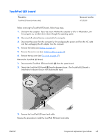
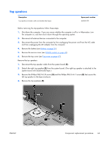
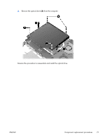
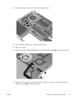
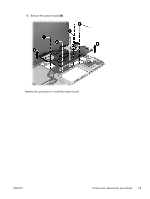
Reverse this procedure to install the top speakers and cable. Optical drive Description DVD±RW and CD-RW Super Multi Double-Layer FX Combo Drive (includes mounting brackets, connector board, and connector cable) Spare part number 668835-001 Before removing the optical drive, follow these steps: 1. Shut down the computer. If you are unsure whether the computer is off or in Hibernation, turn the computer on, and then shut it down through the operating system. 2. Disconnect all external devices connected to the computer. 3. Disconnect the power from the computer by first unplugging the power cord from the AC outlet and then unplugging the AC adapter from the computer. 4. Remove the battery (see Battery on page 35), and then remove the following components: a. Sservice cover (see WLAN module on page 42) b. Top cover (see Top cover on page 47) c. Top speakers (see Top speakers on page 69) Remove the optical drive: 1. Release the ZIF connector to which the optical drive cable is connected, and then disconnect the optical drive cable (1) from the system board. 2. Remove the four Phillips PM2.0×2.8 screws (2) that secure the optical drive to the computer. 70 Chapter 4 Removal and replacement procedures ENWW
-
 1
1 -
2
-
3
-
4
-
5
-
6
-
7
-
8
-
9
-
10
-
11
-
12
-
13
-
14
-
15
-
16
-
17
-
18
-
19
-
20
-
21
-
22
-
23
-
24
-
25
-
26
-
27
-
28
-
29
-
30
-
31
-
32
-
33
-
34
-
35
-
36
-
37
-
38
-
39
-
40
-
41
-
42
-
43
-
44
-
45
-
46
-
47
-
48
-
49
-
50
-
51
-
52
-
53
-
54
-
55
-
56
-
57
-
58
-
59
-
60
-
61
-
62
-
63
-
64
-
65
-
66
-
67
-
68
-
69
-
70
-
71
-
72
-
 73
73 -
 74
74 -
 75
75 -
 76
76 -
 77
77 -
 78
78 -
 79
79 -
 80
80 -
 81
81 -
 82
82 -
 83
83 -
84
-
85
-
86
-
87
-
88
-
89
-
90
-
91
-
92
-
93
-
94
-
95
-
96
-
97
-
98
-
99
-
100
-
101
-
102
-
103
-
104
-
105
-
106
-
107
-
108
-
109
-
110
-
111
-
112
-
113
-
114
-
115
-
116
-
117
-
118
-
119
-
120
-
121
-
122
-
123
-
124
 |
 |
