HP ENVY 15-3033cl HP ENVY 15 - Maintenance and Service Guide - Page 84
Fan/heat sink assembly, Remove the fan/heat sink assembly
 |
View all HP ENVY 15-3033cl manuals
Add to My Manuals
Save this manual to your list of manuals |
Page 84 highlights
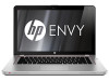
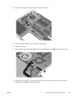
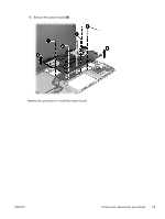
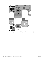
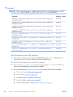
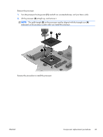
Fan/heat sink assembly NOTE: The fan/heat sink assembly spare part kit includes replacement thermal material. Replacement thermal material is also available in the Thermal Material Kit, spare part number 668848-001. Description For use on computer models equipped with USB 3.0 capability For use on computer models equipped with USB 2.0 capability Spare part number 690006-001 668827-001 NOTE: To properly ventilate the computer, allow at least 7.6 cm (3 in) of clearance on the left side of the computer. The computer uses an electric fan for ventilation. The fan is controlled by a temperature sensor and is designed to turn on automatically when high temperature conditions exist. These conditions are affected by high external temperatures, system power consumption, power management/battery conservation configurations, battery fast charging, and software requirements. Exhaust air is displaced through the ventilation grill located on the left side of the computer. Before removing the fan/heat sink assembly, follow these steps: 1. Shut down the computer. If you are unsure whether the computer is off or in Hibernation, turn the computer on, and then shut it down through the operating system. 2. Disconnect all external devices connected to the computer. 3. Disconnect the power from the computer by first unplugging the power cord from the AC outlet and then unplugging the AC adapter from the computer. 4. Remove the battery (see Battery on page 35), and then remove the following components: a. Service cover (see WLAN module on page 42) b. Top cover (see Top cover on page 47) c. Top speakers (see Top speakers on page 69) d. System board (see System board on page 72) Remove the fan/heat sink assembly: 1. Turn the system board upside down, with the front toward you. 2. Disconnect the 2 fan cables from the system board. 3. Following the 1 through 6 sequence stamped into the fan/heat sink assembly, loosen the six captive screws (2) that secure the fan/heat sink assembly to the system board. NOTE: Due to the adhesive quality of the thermal material located between the heat sink and system board components, it may be necessary to move the fan/heat sink assembly from side to side to detach it. 4. Remove the fan/heat sink assembly (3). 76 Chapter 4 Removal and replacement procedures ENWW
-
 1
1 -
2
-
3
-
4
-
5
-
6
-
7
-
8
-
9
-
10
-
11
-
12
-
13
-
14
-
15
-
16
-
17
-
18
-
19
-
20
-
21
-
22
-
23
-
24
-
25
-
26
-
27
-
28
-
29
-
30
-
31
-
32
-
33
-
34
-
35
-
36
-
37
-
38
-
39
-
40
-
41
-
42
-
43
-
44
-
45
-
46
-
47
-
48
-
49
-
50
-
51
-
52
-
53
-
54
-
55
-
56
-
57
-
58
-
59
-
60
-
61
-
62
-
63
-
64
-
65
-
66
-
67
-
68
-
69
-
70
-
71
-
72
-
73
-
74
-
75
-
76
-
77
-
78
-
 79
79 -
 80
80 -
 81
81 -
 82
82 -
 83
83 -
 84
84 -
 85
85 -
 86
86 -
 87
87 -
 88
88 -
 89
89 -
90
-
91
-
92
-
93
-
94
-
95
-
96
-
97
-
98
-
99
-
100
-
101
-
102
-
103
-
104
-
105
-
106
-
107
-
108
-
109
-
110
-
111
-
112
-
113
-
114
-
115
-
116
-
117
-
118
-
119
-
120
-
121
-
122
-
123
-
124
 |
 |