HP LH4r Compaq 4000/7000 Racks Installation Guide
HP LH4r - NetServer - 256 MB RAM Manual
 |
View all HP LH4r manuals
Add to My Manuals
Save this manual to your list of manuals |
HP LH4r manual content summary:
- HP LH4r | Compaq 4000/7000 Racks Installation Guide - Page 1
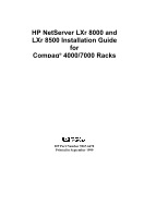
HP NetServer LXr 8000 and LXr 8500 Installation Guide for Compaq® 4000/7000 Racks HP Part Number 5967-6670 Printed in September 1999 - HP LH4r | Compaq 4000/7000 Racks Installation Guide - Page 2
-Packard Company. Audience Assumptions The guide is for the person who installs, administers, and troubleshoots LAN servers. Hewlett-Packard Company assumes you are qualified in the following areas: • You are qualified in the servicing of - HP LH4r | Compaq 4000/7000 Racks Installation Guide - Page 3
Contents About This Guide 1 1 Introduction...3 Compaq Rack-Optimized Kit 3 Order of Installation Operations 4 Compaq Rack Precautions 5 Tools ...8 Terms...8 2 Preparing the HP NetServer 9 Overview of HP NetServer Preparation 9 Disconnect the HP NetServer 10 Extend the HP NetServer 11 Remove - HP LH4r | Compaq 4000/7000 Racks Installation Guide - Page 4
Contents Install the Nameplate 38 Install the Compaq Rack Front Bezel 40 A Warranty and Support 41 Hardware Accessories Limited Warranty 41 HP Repair and Telephone Support 42 Index...43 iv - HP LH4r | Compaq 4000/7000 Racks Installation Guide - Page 5
guide that came with the HP NetServer for instructions on adding accessories to and configuring the HP NetServer. This guide HP NetServer for the Compaq rack (Chapter 2) l Preparing the Compaq rack (Chapter 3) l Installing the HP NetServer in the Compaq rack (Chapter 4) l Warranty and support - HP LH4r | Compaq 4000/7000 Racks Installation Guide - Page 6
- HP LH4r | Compaq 4000/7000 Racks Installation Guide - Page 7
enclosures and were not designed for Compaq racks. Complete and mail the post card in the top tray of the HP NetServer to receive the kit that contains the nameplate, front bezel, control panel bezel, and LCD cover optimized for Compaq racks. Figure 1-1 shows these items. - HP LH4r | Compaq 4000/7000 Racks Installation Guide - Page 8
first install the HP NetServer in the HP NetServer in the Compaq rack before you receive the Compaq rack-optimized kit, refer to Chapters 3 and 4 to prepare the Compaq rack and install the HP NetServer in the rack. After you receive the kit, refer to Chapters 2 and 4 for installation instructions - HP LH4r | Compaq 4000/7000 Racks Installation Guide - Page 9
bezel, 1. Prepare Compaq rack (Chapter 3). and LCD cover (Chapter 2). 2. Install new LCD cover and new control panel bezel (Chapter 2). 2. Install HP NetServer into rack with existing LCD cover and control panel bezel, but no front bezel (Chapter 4). 3. Prepare Compaq rack (Chapter 3). 3. After - HP LH4r | Compaq 4000/7000 Racks Installation Guide - Page 10
. This feature consists of two "feet" at the front of the base of the enclosure and, if you are installing this HP NetServer in a single rack enclosure, two "feet" each on the left and right sides of the enclosure (see Figure 1-2). Side Stabilizing "Feet" (Both Sides) Front - HP LH4r | Compaq 4000/7000 Racks Installation Guide - Page 11
incompatible. An appropriate PDU must be ordered. • Use APC® uninterruptible power supplies (UPS) with HP NetServers. APC offers mounting kits for Compaq rack enclosures. This HP NetServer is not supported in a rack enclosure under circumstances other than those listed above. See the "Warranty and - HP LH4r | Compaq 4000/7000 Racks Installation Guide - Page 12
following tools are required to install the HP NetServer in a Compaq rack: l T15 Torx® driver l Small thin flat-bladed screwdriver l end of the slide (see Figure 3-3). The equipment enclosure into which the HP NetServer will be installed. Industry standard measurement (1.75 inches / 44.45 mm - HP LH4r | Compaq 4000/7000 Racks Installation Guide - Page 13
the Compaq rack. This chapter describes how to prepare the HP NetServer for the Compaq rack-optimized front bezel. The instructions in this chapter are summarized in the list below. l If the HP NetServer is connected, disconnect it. l If the HP NetServer is in a rack, extend it. l Remove the bezel - HP LH4r | Compaq 4000/7000 Racks Installation Guide - Page 14
the backlight on the LCD display is on, standby power is still on. If the HP NetServer is already connected, do the following to disconnect it: 1. Log off all users. Back-up files. Follow instructions in your network operating system (NOS) documentation to properly shut down all networking software - HP LH4r | Compaq 4000/7000 Racks Installation Guide - Page 15
Chapter 2 Preparing the HP NetServer Extend the HP NetServer If the HP NetServer is already installed in a Compaq rack (without a front bezel), do the following to extend the HP NetServer: 1. Remove the four screws that secure the HP NetServer to the rack columns, as shown in Figure 2-1. Figure - HP LH4r | Compaq 4000/7000 Racks Installation Guide - Page 16
Chapter 2 Preparing the HP NetServer 2. To extend the HP NetServer from the rack, pull on the handle indicated in Figure 2-2. Handle Figure 2-2. Pull the Handle to Extend the HP NetServer from the Rack CAUTION When the HP NetServer is extended from the rack, do not lean on it or place extra - HP LH4r | Compaq 4000/7000 Racks Installation Guide - Page 17
Chapter 2 Preparing the HP NetServer Remove Bezel Latch If a bezel latch is mounted on the right side of the HP NetServer, remove it to avoid interference with the Compaq rack front bezel. To remove the bezel latch, remove the screw indicated in Figure 2-3. Figure 2-3. Removing the Bezel Latch 13 - HP LH4r | Compaq 4000/7000 Racks Installation Guide - Page 18
Remove the Control Panel Bezel NOTE Do not remove the original HP rack-optimized control panel bezel until you have received the Compaq , and gently pull the control panel bezel away from the HP NetServer. Control Panel Bezel Snap Latch (2 Places) Figure 2-4. Removing the Control Panel Bezel 14 - HP LH4r | Compaq 4000/7000 Racks Installation Guide - Page 19
Chapter 2 Preparing the HP NetServer Remove the Top Cover, Fan Cover, Fans, and Fan one half-inch (1 cm), as shown in Figure 2-5. Screws Top Cover Figure 2-5. Removing the Entire Top Cover (HP NetServer LXr 8500 Shown) 2. Lift off the top cover, as shown in Figure 2-5. 3. Remove the screw on - HP LH4r | Compaq 4000/7000 Racks Installation Guide - Page 20
Chapter 2 Preparing the HP NetServer 4. Pull the fan cover forward, and then lift the front of it about 1 inch (3 cm). 5. Push the fan cover backwards, and lift it off. 6. - HP LH4r | Compaq 4000/7000 Racks Installation Guide - Page 21
7. Remove the three screws from the front of the fan cage, as shown in Figure 2-8. Figure 2-8. Removing the Fan Cage (HP NetServer LXr 8500 Shown) 8. Remove the two screws from the sides of the chassis, as shown in Figure 2-8. 9. Remove the fan cage by lifting it - HP LH4r | Compaq 4000/7000 Racks Installation Guide - Page 22
Chapter 2 Preparing the HP NetServer Disconnect the LCD Cables A ribbon cable and a twisted-pair cable Top Flap of Ribbon Cable Connector Processor Tray Figure 2-9. Disconnecting the LCD Cables (HP NetServer LXr 8500 Shown) CAUTION When disconnecting the LCD cables, pull the connector straight - HP LH4r | Compaq 4000/7000 Racks Installation Guide - Page 23
Chapter 2 Preparing the HP NetServer Remove the Existing LCD Cover WARNING The LCD cover Spring Finger (12 Places) LCD LCD Assembly Detail Figure 2-10. Removing Screws and LCD Assembly (HP NetServer LXr 8500 Shown) 2. Remove the two screws from the sides of the LCD cover as shown in Figure 2- - HP LH4r | Compaq 4000/7000 Racks Installation Guide - Page 24
When the LCD assembly is lifted high enough, the upper two posts on the HP NetServer are in the wide part of the upper two slots on the LCD to damage the LCD cables. Retaining Spring Slots for Posts on Front of HP NetServer (4 Places) Twisted-Pair Cable LCD Rear Half of Existing LCD Cover - HP LH4r | Compaq 4000/7000 Racks Installation Guide - Page 25
Chapter 2 Preparing the HP NetServer Install the New LCD Cover WARNING The LCD cover contains sheet metal with sharp edges. Handle it carefully to avoid injury. Do the following - HP LH4r | Compaq 4000/7000 Racks Installation Guide - Page 26
Chapter 2 Preparing the HP NetServer 2. Thread the LCD power cord and ribbon cable through the rectangular hole in the rear half of the new LCD cover, as shown in - HP LH4r | Compaq 4000/7000 Racks Installation Guide - Page 27
, be careful not to pinch the LCD cables between the LCD assembly and the front of the HP NetServer. 7. Position the slots on the rear half of the LCD cover over the posts on the processor tray. Gently push the LCD assembly onto - HP LH4r | Compaq 4000/7000 Racks Installation Guide - Page 28
Chapter 2 Preparing the HP NetServer Reconnect the LCD Cables CAUTION When connecting the LCD pair Cable Connector Top Flap of Ribbon Cable Connector Figure 2-15. Reconnecting the LCD Cables (HP NetServer LXr 8500 Shown) 2. Push the twisted pair connector onto the corresponding socket, as shown - HP LH4r | Compaq 4000/7000 Racks Installation Guide - Page 29
Chapter 2 Preparing the HP NetServer Reinstall the Fan Cage, Fans, Fan Cover, and Top Cover not to damage the light pipes on the underside of the cage. Figure 2-16. Reinstall the Fan Cage (HP NetServer LXr 8500 Shown) 2. Lower the fan cage into the chassis. Ensure that the tabs on the front - HP LH4r | Compaq 4000/7000 Racks Installation Guide - Page 30
3. Install all six fans. Orient them with their arrow labels pointing to the rear of the HP NetServer. The fans are keyed so that they must be oriented correctly before they can be inserted fully, with the top of the fan flush - HP LH4r | Compaq 4000/7000 Racks Installation Guide - Page 31
one half-inch (1 cm) to the rear of its normal position when closed. See Figure 2-18. Screws Top Cover Figure 2-18. Reinstalling the Top Cover (HP NetServer LXr 8500 Shown) 6. Push the top cover forward until the slots in its front edge line up with the screw holes on the chassis - HP LH4r | Compaq 4000/7000 Racks Installation Guide - Page 32
on the left and right ends of the control panel bezel, and gently push those latches into the two slots on the front of the HP NetServer indicated in the figure. Control Panel Bezel Snap Latch (2 Places) Figure 2-19. Installing the New Control Panel Bezel 28 - HP LH4r | Compaq 4000/7000 Racks Installation Guide - Page 33
shown in Figure 1-2. Do the following to prepare the Compaq rack for the HP NetServer: l Determine where to install the NetServer in the rack. l Mark the rack columns. The HP NetServer LXr 8000 or 8500 measures 7 EIA units tall. Mark the Installation Holes Follow the instructions below to mark holes - HP LH4r | Compaq 4000/7000 Racks Installation Guide - Page 34
for Installation 3. Now mark two holes on each of the front columns to use for the cage nuts where the HP NetServer-attachment screws secure to the columns. 4. To mark the HP NetServer-attachment holes on the front columns (refer to Figure 3-1), count up from the bottom of the installation location - HP LH4r | Compaq 4000/7000 Racks Installation Guide - Page 35
Chapter 3 Preparing the Rack Install the Cage Nuts Once you have marked the twelve holes, install a supplied cage nut in each marked hole on all columns, as shown in Figure 3-2. Cage Nut Column Figure 3-2. Installing Cage Nuts Adjust the Slides Prepare both slides for mounting, as shown in - HP LH4r | Compaq 4000/7000 Racks Installation Guide - Page 36
Chapter 3 Preparing the Rack 1. Loosen the two screws on the rear flange of the slide, but leave them in place. 2. Extend the rear flange by pushing it outward until the screws stop it. 3. Tighten the screws. NOTE The slides do not come apart; they are one piece. Mount the Slides 1. Orient each - HP LH4r | Compaq 4000/7000 Racks Installation Guide - Page 37
mounted in the Compaq rack, do the following to mount it: l Remove the power supply modules. l Mount the HP NetServer on the slides. l Reinstall the power supply modules. After the HP NetServer is mounted in the rack, do the following to install the Compaq rack-optimized front bezel: l Install the - HP LH4r | Compaq 4000/7000 Racks Installation Guide - Page 38
NetServer to reduce the weight and improve stability, as shown in Figure 4-1. Figure 4-1. Removing Power Supply Modules (Shown for HP NetServer LXr 8500) WARNING Do not touch any metal object to the power supply connector contacts. High electrical charges may be stored in the module - HP LH4r | Compaq 4000/7000 Racks Installation Guide - Page 39
(2 more on other side) Figure 4-2. Lifting the Server Onto the Slide Members 2. Using at least two people, lift the HP NetServer by using the lifting handles on each side. Move the HP NetServer in between the extended slide members and position it so that the handles are resting on the slide members - HP LH4r | Compaq 4000/7000 Racks Installation Guide - Page 40
Chassis 3. Line up the mounting holes in the slide members with the holes in the HP NetServer chassis, insert the four screws on each side and tighten them, as shown in handles and screws for later use, in case you need to remove the HP NetServer and ship it. Figure 4-4. Removing Lifting Handles 36 - HP LH4r | Compaq 4000/7000 Racks Installation Guide - Page 41
Chapter 4 Installing into the Rack 5. On both slide members, simultaneously depress the lockout releases shown in Figure 4-5. Then push the HP NetServer completely into the rack enclosure. Figure 4-5. Location of Lockout Releases 6. Install two screws through the two holes on either side of the - HP LH4r | Compaq 4000/7000 Racks Installation Guide - Page 42
module may cause data corruption or loss. Data corruption or loss due to an incorrectly-installed power supply module is not covered by the HP warranty. Install the Nameplate Prepare the Compaq rack-optimized front bezel by attaching the appropriate nameplate to it, as follows: 1. Orient the Compaq - HP LH4r | Compaq 4000/7000 Racks Installation Guide - Page 43
Chapter 4 Slots Holes for Studs Installing into the Rack Nameplate HP Logo Compaq Rack-Optimized Front Bezel Tabs Figure 4-7. Attaching Nameplate to Compaq Rack-Optimized Front Bezel 39 - HP LH4r | Compaq 4000/7000 Racks Installation Guide - Page 44
the Rack Install the Compaq Rack Front Bezel Install the front bezel optimized for Compaq racks as follows: 1. Hold the bezel in front of the HP NetServer, as shown in Figure 4-8. Align the four studs on the back of the bezel with the four oval holes indicated in the figure. Figure - HP LH4r | Compaq 4000/7000 Racks Installation Guide - Page 45
A Warranty and Support Refer to the HP NetServer Warranty and Service/Support Booklet provided with your original HP NetServer system documentation for the warranty limitations, customer responsibilities, and other terms and conditions. CAUTION Improper installation of HP rack mount components - HP LH4r | Compaq 4000/7000 Racks Installation Guide - Page 46
diagnostic programs before a replacement will be dispatched or an on-site visit is authorized. HP Repair and Telephone Support Refer to the HP NetServer Warranty and Service/Support Booklet supplied with your HP NetServer system documentation for instructions on how to obtain HP repair and telephone - HP LH4r | Compaq 4000/7000 Racks Installation Guide - Page 47
14, 28 front, 9, 38, 40 Bezel latch, 13 C Cage nut, 8 Caution extended HP NetServer, 12 fan cage light pipes, 17, 18, 24, 25 fan removal, 16 improper panel bezel, 28 fan cage, fans, and fan cover, 25 front bezel, 40 HP NetServer into rack, 33 LCD cover, 21 nameplate, 38 power supply modules, 38 top - HP LH4r | Compaq 4000/7000 Racks Installation Guide - Page 48
HP NetServer, 35 Light pipes, fan cage, 17, 18, 24, 25 Lockout releases, 37 M Marking installation rack holes, 29 Mass storage devices, 7 Mounting HP Overview HP NetServer rack, 29 HP NetServer, 9 S Securing HP NetServer, 37 Slide, 8 fastening HP NetServer, levels, 10 lifting HP NetServer, 33 power
-
 1
1 -
 2
2 -
 3
3 -
 4
4 -
 5
5 -
 6
6 -
 7
7 -
8
-
9
-
10
-
11
-
12
-
13
-
14
-
15
-
16
-
17
-
18
-
19
-
20
-
21
-
22
-
23
-
24
-
25
-
26
-
27
-
28
-
29
-
30
-
31
-
32
-
33
-
34
-
35
-
36
-
37
-
38
-
39
-
40
-
41
-
42
-
43
-
44
-
45
-
46
-
47
-
48
 |
 |

HP NetServer LXr 8000 and
LXr 8500 Installation Guide
for
Compaq
®
4000/7000 Racks
HP Part Number 5967-6670
Printed in September 1999