HP Mini 1000 HP Mini 1000 NetBook - Maintenance and Service Guide - Page 47
Remove the top cover., Reverse this procedure to install the top cover.
 |
View all HP Mini 1000 manuals
Add to My Manuals
Save this manual to your list of manuals |
Page 47 highlights
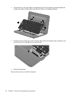
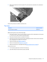
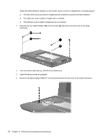
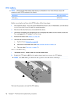
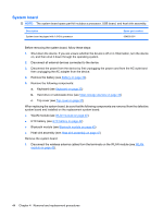
7. Lift the rear edge of the top cover (1), swing it up, and then slide it back slightly to rest against the display assembly at an angle (2). 8. Release the ZIF connector (1) to which the TouchPad button board cable is connected, and then disconnect the cable (2) from the system board. 9. Remove the top cover. Reverse this procedure to install the top cover. Component replacement procedures 39
-
 1
1 -
2
-
3
-
4
-
5
-
6
-
7
-
8
-
9
-
10
-
11
-
12
-
13
-
14
-
15
-
16
-
17
-
18
-
19
-
20
-
21
-
22
-
23
-
24
-
25
-
26
-
27
-
28
-
29
-
30
-
31
-
32
-
33
-
34
-
35
-
36
-
37
-
38
-
39
-
40
-
41
-
 42
42 -
 43
43 -
 44
44 -
 45
45 -
 46
46 -
 47
47 -
 48
48 -
 49
49 -
 50
50 -
 51
51 -
 52
52 -
53
-
54
-
55
-
56
-
57
-
58
-
59
-
60
-
61
-
62
-
63
-
64
-
65
-
66
-
67
-
68
-
69
-
70
-
71
-
72
-
73
-
74
-
75
-
76
-
77
-
78
-
79
-
80
-
81
-
82
-
83
-
84
-
85
-
86
-
87
-
88
-
89
-
90
-
91
-
92
-
93
-
94
-
95
-
96
-
97
-
98
-
99
-
100
-
101
-
102
-
103
-
104
-
105
 |
 |

7.
Lift the rear edge of the top cover
(1)
, swing it up, and then slide it back slightly to rest against the
display assembly at an angle
(2)
.
8.
Release the ZIF connector
(1)
to which the TouchPad button board cable is connected, and then
disconnect the cable
(2)
from the system board.
9.
Remove the top cover.
Reverse this procedure to install the top cover.
Component replacement procedures
39