HP Mini 1000 HP Mini 1000 NetBook - Maintenance and Service Guide - Page 61
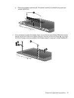
Remove the eight black Phillips PM2.0×4.0 screws that secure the display panel to the display
 |
View all HP Mini 1000 manuals
Add to My Manuals
Save this manual to your list of manuals |
Page 61 highlights
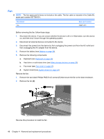
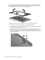
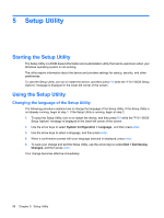
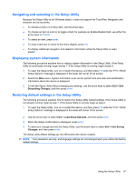
c. Remove the two black Phillips PM2.0×4.0 screws (1) that secure the webcam module to the display enclosure, and then remove the webcam module (2). The webcam module is available using spare part number 504594-001. 7. If it is necessary to replace the display panel, perform the following steps: a. Remove the eight black Phillips PM2.0×4.0 screws that secure the display panel to the display enclosure. b. Remove the wireless antenna cables (1) from the clips and routing channels built into the display and brackets (2). Component replacement procedures 53
-
 1
1 -
2
-
3
-
4
-
5
-
6
-
7
-
8
-
9
-
10
-
11
-
12
-
13
-
14
-
15
-
16
-
17
-
18
-
19
-
20
-
21
-
22
-
23
-
24
-
25
-
26
-
27
-
28
-
29
-
30
-
31
-
32
-
33
-
34
-
35
-
36
-
37
-
38
-
39
-
40
-
41
-
42
-
43
-
44
-
45
-
46
-
47
-
48
-
49
-
50
-
51
-
52
-
53
-
54
-
55
-
 56
56 -
 57
57 -
 58
58 -
 59
59 -
 60
60 -
 61
61 -
 62
62 -
 63
63 -
 64
64 -
 65
65 -
 66
66 -
67
-
68
-
69
-
70
-
71
-
72
-
73
-
74
-
75
-
76
-
77
-
78
-
79
-
80
-
81
-
82
-
83
-
84
-
85
-
86
-
87
-
88
-
89
-
90
-
91
-
92
-
93
-
94
-
95
-
96
-
97
-
98
-
99
-
100
-
101
-
102
-
103
-
104
-
105
 |
 |

c.
Remove the two black Phillips PM2.0×4.0 screws
(1)
that secure the webcam module to the
display enclosure, and then remove the webcam module
(2)
. The webcam module is available
using spare part number 504594-001.
7.
If it is necessary to replace the display panel, perform the following steps:
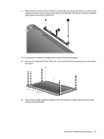
a.
Remove the eight black Phillips PM2.0×4.0 screws that secure the display panel to the display
enclosure.
b.
Remove the wireless antenna cables
(1)
from the clips and routing channels built into the
display and brackets
(2)
.
Component replacement procedures
53