HP Mini 1000 HP Mini 1000 NetBook - Maintenance and Service Guide - Page 54
Grasp the system board at its midpoint, Remove the system board
 |
View all HP Mini 1000 manuals
Add to My Manuals
Save this manual to your list of manuals |
Page 54 highlights
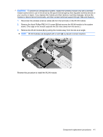
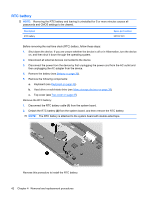
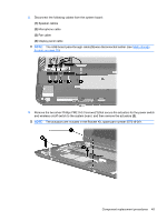
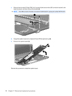
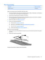
4. Remove the two black Phillips PM2.0×4.0 screws (1) that secure the USB connector bracket to the base enclosure, and then remove the bracket (2). NOTE: The USB connector bracket is included in the Bracket Kit, spare part number 507318-001. 5. Grasp the system board at its midpoint (1) and lift the right side up (2). 6. Remove the system board (3). Reverse the procedure to install the system board. 46 Chapter 4 Removal and replacement procedures
-
 1
1 -
2
-
3
-
4
-
5
-
6
-
7
-
8
-
9
-
10
-
11
-
12
-
13
-
14
-
15
-
16
-
17
-
18
-
19
-
20
-
21
-
22
-
23
-
24
-
25
-
26
-
27
-
28
-
29
-
30
-
31
-
32
-
33
-
34
-
35
-
36
-
37
-
38
-
39
-
40
-
41
-
42
-
43
-
44
-
45
-
46
-
47
-
48
-
 49
49 -
 50
50 -
 51
51 -
 52
52 -
 53
53 -
 54
54 -
 55
55 -
 56
56 -
 57
57 -
 58
58 -
 59
59 -
60
-
61
-
62
-
63
-
64
-
65
-
66
-
67
-
68
-
69
-
70
-
71
-
72
-
73
-
74
-
75
-
76
-
77
-
78
-
79
-
80
-
81
-
82
-
83
-
84
-
85
-
86
-
87
-
88
-
89
-
90
-
91
-
92
-
93
-
94
-
95
-
96
-
97
-
98
-
99
-
100
-
101
-
102
-
103
-
104
-
105
 |
 |
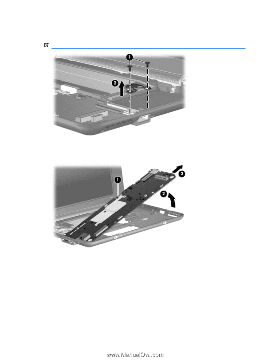
4.
Remove the two black Phillips PM2.0×4.0 screws
(1)
that secure the USB connector bracket to the
base enclosure, and then remove the bracket
(2)
.
NOTE:
The USB connector bracket is included in the Bracket Kit, spare part number 507318-001.
5.
Grasp the system board at its midpoint
(1)
and lift the right side up
(2)
.
6.
Remove the system board
(3)
.
Reverse the procedure to install the system board.
46
Chapter 4
Removal and replacement procedures