HP Mini 1000 HP Mini 1000 NetBook - Maintenance and Service Guide - Page 57
Display assembly, Keyboard see
 |
View all HP Mini 1000 manuals
Add to My Manuals
Save this manual to your list of manuals |
Page 57 highlights
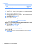
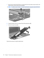
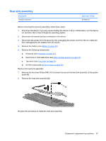
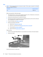
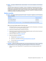
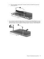
NOTE: To properly ventilate the device, allow at least a 7.6-cm (3-inch) clearance on the left side of the device. The device uses an electric fan for ventilation. The fan is controlled by a temperature sensor and is designed to turn on automatically when high temperature conditions exist. These conditions are affected by high external temperatures, system power consumption, power management/battery conservation configurations, battery fast charging, and software requirements. Exhaust air is displaced through the ventilation grill located on the left side of the device. Display assembly NOTE: Each display assembly spare part kit includes 1 microphone, 2 speakers, and 2 WLAN antenna transceivers/cables). Description Spare part number 8.9-inch WSVGA BrightView 507309-001 10.2-inch WSVGA AntiGlare 507310-001 Refer to Display assembly components on page 15, for more display assembly component spare part information. Before removing the display assembly, follow these steps: 1. Shut down the device. If you are unsure whether the device is off or in Hibernation, turn the device on, and then shut it down through the operating system. 2. Disconnect all external devices connected to the device. 3. Disconnect the power from the device by first unplugging the power cord from the AC outlet and then unplugging the AC adapter from the device. 4. Remove the battery (see Battery on page 30). 5. Remove the following components: a. Keyboard (see Keyboard on page 33) b. Hard drive or solid-state drive (see Mass storage devices on page 35) c. Top cover (see Top cover on page 37) Remove the display assembly: CAUTION: Support the display assembly when removing the following screws. Failure to support the display assembly can result in damage to the display assembly and other device components. 1. Remove the four silver Phillips PM2.5×7.0 screws (1) that secure the display assembly to the device. Component replacement procedures 49
-
 1
1 -
2
-
3
-
4
-
5
-
6
-
7
-
8
-
9
-
10
-
11
-
12
-
13
-
14
-
15
-
16
-
17
-
18
-
19
-
20
-
21
-
22
-
23
-
24
-
25
-
26
-
27
-
28
-
29
-
30
-
31
-
32
-
33
-
34
-
35
-
36
-
37
-
38
-
39
-
40
-
41
-
42
-
43
-
44
-
45
-
46
-
47
-
48
-
49
-
50
-
51
-
 52
52 -
 53
53 -
 54
54 -
 55
55 -
 56
56 -
 57
57 -
 58
58 -
 59
59 -
 60
60 -
 61
61 -
 62
62 -
63
-
64
-
65
-
66
-
67
-
68
-
69
-
70
-
71
-
72
-
73
-
74
-
75
-
76
-
77
-
78
-
79
-
80
-
81
-
82
-
83
-
84
-
85
-
86
-
87
-
88
-
89
-
90
-
91
-
92
-
93
-
94
-
95
-
96
-
97
-
98
-
99
-
100
-
101
-
102
-
103
-
104
-
105
 |
 |