HP OMEN X 17-ap000 OMEN X by 17 Laptop PC Maintenance and Service Guide - Page 50
Removal and replacement procedures for authorized service provider parts
 |
View all HP OMEN X 17-ap000 manuals
Add to My Manuals
Save this manual to your list of manuals |
Page 50 highlights
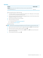
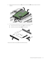
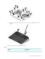
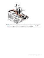
6 Removal and replacement procedures for authorized service provider parts CAUTION: Components described in this chapter should be accessed only by an authorized service provider. Accessing these parts can damage the computer or void the warranty. Component replacement procedures NOTE: Details about your computer, including model, serial number, product key, and length of warranty, are on the service tag at the bottom of your computer. See Labels on page 17 for details. NOTE: HP continually improves and changes product parts. For complete and current information on supported parts for your computer, go to http://partsurfer.hp.com, select your country or region, and then follow the on-screen instructions. There may be as many as 85 screws that must be removed, replaced, and/or loosened when servicing the parts described in this chapter. Make special note of each screw size and location during removal and replacement. Base enclosure Description Base enclosure Spare part number 940585-001 Before removing the base enclosure, follow these steps: 1. Turn off the computer. If you are unsure whether the computer is off or in Hibernation, turn the computer on, and then shut it down through the operating system. 2. Disconnect the power from the computer by first unplugging the power cord from the AC outlet and then unplugging the AC adapter from the computer. 3. Disconnect all external devices connected to the computer. 4. Position the computer upside down on a flat surface. Remove the base enclosure: 1. Loosen but do not remove the two screws from the bottom cover (1). Remove the remaining eight Phillips screws (2) from the bottom cover. 38 Chapter 6 Removal and replacement procedures for authorized service provider parts
-
 1
1 -
2
-
3
-
4
-
5
-
6
-
7
-
8
-
9
-
10
-
11
-
12
-
13
-
14
-
15
-
16
-
17
-
18
-
19
-
20
-
21
-
22
-
23
-
24
-
25
-
26
-
27
-
28
-
29
-
30
-
31
-
32
-
33
-
34
-
35
-
36
-
37
-
38
-
39
-
40
-
41
-
42
-
43
-
44
-
 45
45 -
 46
46 -
 47
47 -
 48
48 -
 49
49 -
 50
50 -
 51
51 -
 52
52 -
 53
53 -
 54
54 -
 55
55 -
56
-
57
-
58
-
59
-
60
-
61
-
62
-
63
-
64
-
65
-
66
-
67
-
68
-
69
-
70
-
71
-
72
-
73
-
74
-
75
-
76
-
77
-
78
-
79
-
80
-
81
-
82
-
83
-
84
-
85
-
86
-
87
-
88
-
89
-
90
-
91
 |
 |