HP OMEN X 17-ap000 OMEN X by 17 Laptop PC Maintenance and Service Guide - Page 54
Heat sink with fan, Remove one Phillips screw
 |
View all HP OMEN X 17-ap000 manuals
Add to My Manuals
Save this manual to your list of manuals |
Page 54 highlights
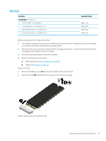
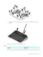
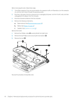
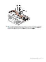
Heat sink with fan NOTE: The heat sink spare parts kit includes replacement thermal material. Description Heat sink with fan (for use only on products equipped with a GTX-1080 processor) Heat sink with fan (for use only on products equipped with a GTX 1070 i7-7700 HQ processor) Heat sink with fan (for use only on products equipped with a GTX 1070 i7-7820 HK processor) Spare part number 940598-001 L00257-001 L00258-001 IMPORTANT: Make special note of each screw and screw lock size and location during removal and replacement. Before removing the heat sink, follow these steps: 1. Turn off the computer. If you are unsure whether the computer is off or in Hibernation, turn the computer on, and then shut it down through the operating system. 2. Disconnect the power from the computer by first unplugging the power cord from the AC outlet and then unplugging the AC adapter from the computer. 3. Disconnect all external devices from the computer. 4. Remove the following components: a. Base enclosure (see Base enclosure on page 38) b. Battery (see Battery on page 31) c. Remove the fan (see Fan on page 41). Remove the heat sink: 1. Remove one Phillips screw (1) on the top left corner of the fan. 2. Remove the three other small screws (2) around the fan. 3. Loosen the eight screws securing the heat sink to the system board (3). 4. Remove the heat sink and fan (4). NOTE: Due to the adhesive quality of the thermal material located between the heat sink and the system board components, it may be necessary to move the heat sink from side to side to detach it. 42 Chapter 6 Removal and replacement procedures for authorized service provider parts
-
 1
1 -
2
-
3
-
4
-
5
-
6
-
7
-
8
-
9
-
10
-
11
-
12
-
13
-
14
-
15
-
16
-
17
-
18
-
19
-
20
-
21
-
22
-
23
-
24
-
25
-
26
-
27
-
28
-
29
-
30
-
31
-
32
-
33
-
34
-
35
-
36
-
37
-
38
-
39
-
40
-
41
-
42
-
43
-
44
-
45
-
46
-
47
-
48
-
 49
49 -
 50
50 -
 51
51 -
 52
52 -
 53
53 -
 54
54 -
 55
55 -
 56
56 -
 57
57 -
 58
58 -
 59
59 -
60
-
61
-
62
-
63
-
64
-
65
-
66
-
67
-
68
-
69
-
70
-
71
-
72
-
73
-
74
-
75
-
76
-
77
-
78
-
79
-
80
-
81
-
82
-
83
-
84
-
85
-
86
-
87
-
88
-
89
-
90
-
91
 |
 |
