HP OMEN X 17-ap000 OMEN X by 17 Laptop PC Maintenance and Service Guide - Page 66
Display assembly, Disconnect all external devices connected to the computer.
 |
View all HP OMEN X 17-ap000 manuals
Add to My Manuals
Save this manual to your list of manuals |
Page 66 highlights
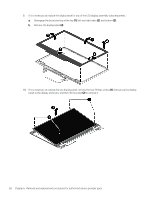
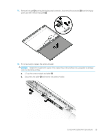
Display assembly Description Antenna, dual Back cover Camera Display bezel Display cable ● For products with non-touch FHD screen with HD camera, 120 Hz ● For products with non-touch UHD screen with HD camera, 120 Hz Hinge Hinge support bracket Raw panel 43.94 cm (17.3") (non-touch screen) ● FHD WLED AntiGlare (1920 x 1080) flat-flat (4.0 mm) UWVA, eDP1.3 + NVSR, Support NVIDIA G-Sync 120Hz ● UHD WLED AntiGlare (3840 x 2160) flat-flat (4.0 mm) UWVA, eDP + PSR, Support NVIDIA G-Sync ● FHD LED AntiGlare (1920 x 1080) flat-flat (4.0 mm) UWVA, eDP + PSR, Support NVIDIA G-Sync Spare part number 940583-001 940584-001 940626-001 940586-001 940593-001 940594-001 940603-001 940604-001 940614-001 940615-001 L12056-001 IMPORTANT: Make special note of each screw and screw lock size and location during removal and replacement. Before removing the display assembly, follow these steps: 1. Shut down the computer. 2. Disconnect the power from the computer by first unplugging the power cord from the AC outlet and then unplugging the AC adapter from the computer. 3. Disconnect all external devices connected to the computer. 4. Remove the following components: a. Base enclosure (see Base enclosure on page 38) b. Battery (see Battery on page 31) c. Speakers (see Speakers on page 45). d. Remove the fans (see Fan on page 41) e. Remove the heat sink (see Heat sink with fan on page 42) f. Remove the system board (see System board on page 47) Remove the display assembly: 1. Remove the 12 Phillips screws from the hinge. 54 Chapter 6 Removal and replacement procedures for authorized service provider parts
-
 1
1 -
2
-
3
-
4
-
5
-
6
-
7
-
8
-
9
-
10
-
11
-
12
-
13
-
14
-
15
-
16
-
17
-
18
-
19
-
20
-
21
-
22
-
23
-
24
-
25
-
26
-
27
-
28
-
29
-
30
-
31
-
32
-
33
-
34
-
35
-
36
-
37
-
38
-
39
-
40
-
41
-
42
-
43
-
44
-
45
-
46
-
47
-
48
-
49
-
50
-
51
-
52
-
53
-
54
-
55
-
56
-
57
-
58
-
59
-
60
-
 61
61 -
 62
62 -
 63
63 -
 64
64 -
 65
65 -
 66
66 -
 67
67 -
 68
68 -
 69
69 -
 70
70 -
 71
71 -
72
-
73
-
74
-
75
-
76
-
77
-
78
-
79
-
80
-
81
-
82
-
83
-
84
-
85
-
86
-
87
-
88
-
89
-
90
-
91
 |
 |
