HP OMEN X 17-ap000 OMEN X by 17 Laptop PC Maintenance and Service Guide - Page 59
System board, Remove the fans see
 |
View all HP OMEN X 17-ap000 manuals
Add to My Manuals
Save this manual to your list of manuals |
Page 59 highlights
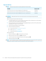
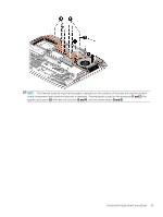
System board Description System board All system boards use the following part numbers: xxxxxx-001 Non-Windows operating systems xxxxxx-601 Windows 10 operating systems ● DSC GTX 1070 8 GB i7-7700 ● GTX 1070 8 GB i7-7820 ● GTX 1080 8 GB i7-7700 ● GTX 1080 8 GB i7-7820 Spare part number 940621-xxx 940622-xxx 940623-xxx 940624-xxx IMPORTANT: Make special note of each screw and screw lock size and location during removal and replacement. Before removing the system board, follow these steps: 1. Shut down the computer. 2. Disconnect the power from the computer by first unplugging the power cord from the AC outlet and then unplugging the AC adapter from the computer. 3. Disconnect all external devices connected to the computer. 4. Remove the following components: a. Base enclosure (see Base enclosure on page 38) b. Battery (see Battery on page 31) c. Speakers (see Speakers on page 45) d. Remove the fans (see Fan on page 41) e. Remove the heatsink (see Heat sink with fan on page 42) NOTE: When replacing the system board, be sure that the following components are removed from the defective system board and installed on the replacement system board: ● WLAN module (see WLAN module on page 50) ● Memory module (see Memory module on page 36) Remove the system board: 1. If they are not already disconnected, disconnect the following cables from the system board (note the routing location of the cables when removing them): NOTE: Use minimal force when lifting the locking bar up on a ZIF connector and disconnecting the cable. (1) Power board cable (2) WLAN antenna cables (3) HDD cable Component replacement procedures 47
-
 1
1 -
2
-
3
-
4
-
5
-
6
-
7
-
8
-
9
-
10
-
11
-
12
-
13
-
14
-
15
-
16
-
17
-
18
-
19
-
20
-
21
-
22
-
23
-
24
-
25
-
26
-
27
-
28
-
29
-
30
-
31
-
32
-
33
-
34
-
35
-
36
-
37
-
38
-
39
-
40
-
41
-
42
-
43
-
44
-
45
-
46
-
47
-
48
-
49
-
50
-
51
-
52
-
53
-
 54
54 -
 55
55 -
 56
56 -
 57
57 -
 58
58 -
 59
59 -
 60
60 -
 61
61 -
 62
62 -
 63
63 -
 64
64 -
65
-
66
-
67
-
68
-
69
-
70
-
71
-
72
-
73
-
74
-
75
-
76
-
77
-
78
-
79
-
80
-
81
-
82
-
83
-
84
-
85
-
86
-
87
-
88
-
89
-
90
-
91
 |
 |
