HP Pavilion 12-b000 Maintenance and Service Guide - Page 39
Reverse this procedure to install the WLAN module., be installed on the antenna connector
 |
View all HP Pavilion 12-b000 manuals
Add to My Manuals
Save this manual to your list of manuals |
Page 39 highlights
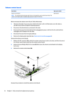
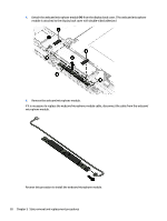
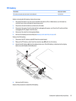
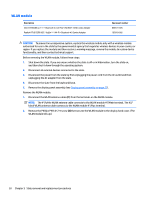
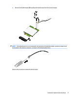
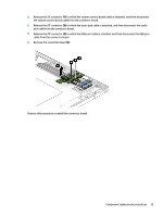
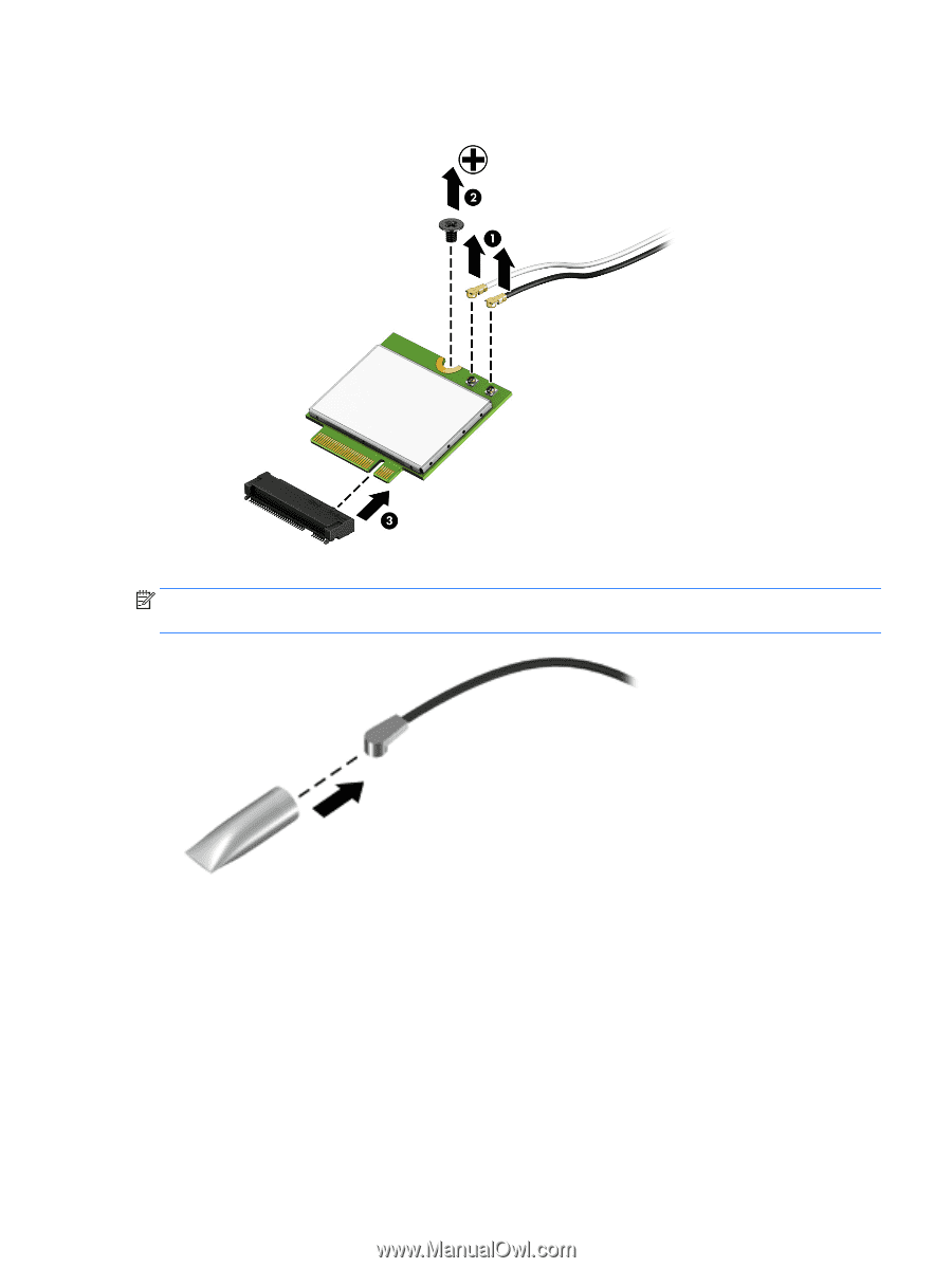
3. Remove the WLAN module (3) by pulling the module away from the slot at an angle. NOTE: If the WLAN antenna is not connected to the terminal on the WLAN module, a protective sleeve must be installed on the antenna connector, as shown in the following illustration. Reverse this procedure to install the WLAN module. Component replacement procedures 31
-
 1
1 -
2
-
3
-
4
-
5
-
6
-
7
-
8
-
9
-
10
-
11
-
12
-
13
-
14
-
15
-
16
-
17
-
18
-
19
-
20
-
21
-
22
-
23
-
24
-
25
-
26
-
27
-
28
-
29
-
30
-
31
-
32
-
33
-
 34
34 -
 35
35 -
 36
36 -
 37
37 -
 38
38 -
 39
39 -
 40
40 -
 41
41 -
 42
42 -
 43
43 -
 44
44 -
45
-
46
-
47
-
48
-
49
-
50
-
51
-
52
-
53
-
54
-
55
-
56
-
57
-
58
-
59
-
60
-
61
-
62
-
63
-
64
-
65
-
66
-
67
-
68
-
69
-
70
-
71
-
72
-
73
-
74
-
75
-
76
-
77
-
78
 |
 |
3.
Remove the WLAN module
(3)
by pulling the module away from the slot at an angle.
NOTE:
If the WLAN antenna is not connected to the terminal on the WLAN module, a protective sleeve must
be installed on the antenna connector, as shown in the following illustration.
Reverse this procedure to install the WLAN module.
Component replacement procedures
31