HP Pavilion 12-b000 Maintenance and Service Guide - Page 45
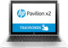
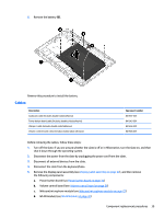
Remove the Philllips PM2.0×3.8 screw, Remove the six Philllips PM2.0×2.2 broadhead screws
 |
View all HP Pavilion 12-b000 manuals
Add to My Manuals
Save this manual to your list of manuals |
Page 45 highlights
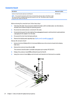
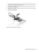
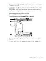
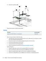
1. Release the ZIF connector (1) to which the USB port cable is attached, and then disconnect the USB port cable from the system board. 2. Release the ZIF connector (2) to which the audio jack cable is attached, and then disconnect the audio jack cable from the system board. 3. Disconnect the left and right speaker cables (3) from the speaker connectors on the system board. 4. Release the ZIF connector (4) to which the power button board cable is attached, and then disconnect the power button board cable from the system board. 5. Disconnect the display panel cable (5) from the system board. 6. Disconnect the RTC battery cable (6) from the system board. 7. Disconnect the webcam/microphone module cable (7) from the system board. 8. Remove the six Philllips PM2.0×2.2 broadhead screws (1) that secure the system board to the display back cover. 9. Remove the Philllips PM2.0×3.8 screw (2) that secures the system board to the display back cover. Component replacement procedures 37
-
 1
1 -
2
-
3
-
4
-
5
-
6
-
7
-
8
-
9
-
10
-
11
-
12
-
13
-
14
-
15
-
16
-
17
-
18
-
19
-
20
-
21
-
22
-
23
-
24
-
25
-
26
-
27
-
28
-
29
-
30
-
31
-
32
-
33
-
34
-
35
-
36
-
37
-
38
-
39
-
 40
40 -
 41
41 -
 42
42 -
 43
43 -
 44
44 -
 45
45 -
 46
46 -
 47
47 -
 48
48 -
 49
49 -
 50
50 -
51
-
52
-
53
-
54
-
55
-
56
-
57
-
58
-
59
-
60
-
61
-
62
-
63
-
64
-
65
-
66
-
67
-
68
-
69
-
70
-
71
-
72
-
73
-
74
-
75
-
76
-
77
-
78
 |
 |
