HP Pavilion 14-ab000 ab000 through 14 - ab099 Maintenance and Service Guide - Page 51
USB Connector board, Disconnect the connector board cable
 |
View all HP Pavilion 14-ab000 manuals
Add to My Manuals
Save this manual to your list of manuals |
Page 51 highlights
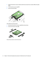
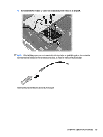
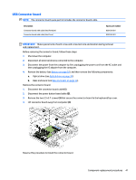
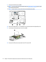
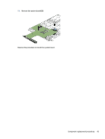
USB Connector board NOTE: The connector board spare part kit includes the connector board cable. Description Connector board with cable (Intel Pentium) Connector board with cable (Intel Core) Spare part number 809109-001 809108-001 IMPORTANT: Make special note of each screw and screw lock size and location during removal and replacement. Before removing the connector board, follow these steps: 1. Shut down the computer. 2. Disconnect all external devices connected to the computer. 3. Disconnect the power from the computer by first unplugging the power cord from the AC outlet and then unplugging the AC adapter from the computer. 4. Remove the battery (see Battery on page 29), and then remove the following components: a. Optical drive (see Optical drive on page 30). b. Base enclosure (see Base enclosure on page 33). Remove the connector board: 1. Disconnect the connector board cable (1). 2. Disconnect the power button board cable (2). 3. Remove the two 2.5×3.7 screws (3) that secure the connector board to the keyboard/top cover. 4. Lift connector board away from computer (4). Reverse this procedure to install the connector board. Component replacement procedures 41
-
 1
1 -
2
-
3
-
4
-
5
-
6
-
7
-
8
-
9
-
10
-
11
-
12
-
13
-
14
-
15
-
16
-
17
-
18
-
19
-
20
-
21
-
22
-
23
-
24
-
25
-
26
-
27
-
28
-
29
-
30
-
31
-
32
-
33
-
34
-
35
-
36
-
37
-
38
-
39
-
40
-
41
-
42
-
43
-
44
-
45
-
 46
46 -
 47
47 -
 48
48 -
 49
49 -
 50
50 -
 51
51 -
 52
52 -
 53
53 -
 54
54 -
 55
55 -
 56
56 -
57
-
58
-
59
-
60
-
61
-
62
-
63
-
64
-
65
-
66
-
67
-
68
-
69
-
70
-
71
-
72
-
73
-
74
-
75
-
76
-
77
-
78
-
79
-
80
-
81
-
82
-
83
-
84
-
85
-
86
-
87
-
88
-
89
-
90
-
91
-
92
-
93
-
94
-
95
-
96
-
97
-
98
-
99
 |
 |
