HP Pavilion 14-ab000 ab000 through 14 - ab099 Maintenance and Service Guide - Page 53
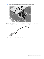
the keyboard backlight cable from the system board select models only.
 |
View all HP Pavilion 14-ab000 manuals
Add to My Manuals
Save this manual to your list of manuals |
Page 53 highlights
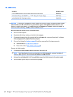
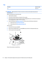
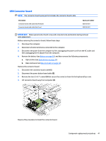
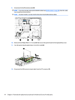
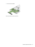
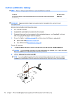
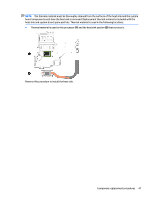
Description Spare part number Equipped with an Pentium N3700 1.60-GHz (SC Turbo up to 2.40-GHz) processor (1600-MHz FSB, 2.00-MB L2 cache, dual core, 6 W), a graphics subsystem with UMA memory, and the Windows 8 Standard operating system 806833-501 Equipped with an Pentium N3700 1.60-GHz (SC Turbo up to 2.40-GHz) processor (1600-MHz FSB, 2.00-MB 806833-001 L2 cache, dual core, 6 W), a graphics subsystem with UMA memory, and a non-Windows 8 operating system IMPORTANT: Make special note of each screw and screw lock size and location during removal and replacement. Before removing the system board, follow these steps: 1. Shut down the computer. 2. Disconnect all external devices connected to the computer. 3. Disconnect the power from the computer by first unplugging the power cord from the AC outlet and then unplugging the AC adapter from the computer. 4. Remove the battery (see Battery on page 29), and then remove the following components: a. Optical drive (see Optical drive on page 30). b. Base enclosure (see Base enclosure on page 33). c. WLAN module(see WLAN module on page 38). d. Memory (see Memory module on page 37). e. Fan (see Fan on page 40). Remove the system board: 1. Release the ZIF connector (1) to which the keyboard cable is attached, and then disconnect the keyboard cable from the system board. 2. Release the ZIF connector (2) to which the keyboard backlight cable is attached, and then disconnect the keyboard backlight cable from the system board (select models only). 3. Release the ZIF connector (3) to which the TouchPad cable is attached, and then disconnect the TouchPad cable from the system board. 4. Release the ZIF connector (4) to which the display panel cable is attached, and then disconnect the display panel cable from the system board. 5. Disconnect the ambient sensor light cable (5) (select models only). 6. Release the ZIF connector (6) to which the hard drive connector cable is attached, and then disconnect the hard drive connector cable from the system board. 7. Disconnect the power connector cable (7). 8. Disconnect the speaker cable (8). Component replacement procedures 43
-
 1
1 -
2
-
3
-
4
-
5
-
6
-
7
-
8
-
9
-
10
-
11
-
12
-
13
-
14
-
15
-
16
-
17
-
18
-
19
-
20
-
21
-
22
-
23
-
24
-
25
-
26
-
27
-
28
-
29
-
30
-
31
-
32
-
33
-
34
-
35
-
36
-
37
-
38
-
39
-
40
-
41
-
42
-
43
-
44
-
45
-
46
-
47
-
 48
48 -
 49
49 -
 50
50 -
 51
51 -
 52
52 -
 53
53 -
 54
54 -
 55
55 -
 56
56 -
 57
57 -
 58
58 -
59
-
60
-
61
-
62
-
63
-
64
-
65
-
66
-
67
-
68
-
69
-
70
-
71
-
72
-
73
-
74
-
75
-
76
-
77
-
78
-
79
-
80
-
81
-
82
-
83
-
84
-
85
-
86
-
87
-
88
-
89
-
90
-
91
-
92
-
93
-
94
-
95
-
96
-
97
-
98
-
99
 |
 |
