HP Pavilion 14-ab000 ab000 through 14 - ab099 Maintenance and Service Guide - Page 66
Display assembly (non-TouchScreen) (select models only
 |
View all HP Pavilion 14-ab000 manuals
Add to My Manuals
Save this manual to your list of manuals |
Page 66 highlights
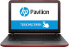
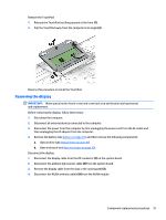
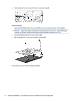
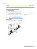
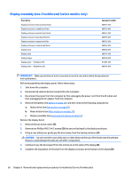
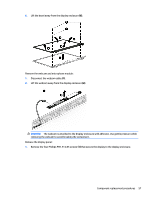
Display assembly (non-TouchScreen) (select models only) Description Display enclosure in blizzard white finish Display enclosure in cobalt blue finish Display enclosure in natural silver finish Display enclosure in peachy pink finish Display enclosure in sunset red finish Display enclosure in violet purple finish Display bezel Display cable Display hinges Display panel - AntiGlare, FHD Display panel - BrightView, HD Spare part number 806737-001 806734-001 806732-001 806735-001 806733-001 806736-001 806744-001 806745-001 806748-001 811081-001 806766-001 IMPORTANT: Make special note of each screw and screw lock size and location during removal and replacement. Before disassembling the display panel, follow these steps: 1. Shut down the computer. 2. Disconnect all external devices connected to the computer. 3. Disconnect the power from the computer by first unplugging the power cord from the AC outlet and then unplugging the AC adapter from the computer. 4. Remove the battery (see Battery on page 29), and then remove the following components: a. Optical drive (see Optical drive on page 30). b. Base enclosure (see Base enclosure on page 33). c. Display assembly (see Removing the display on page 51). Remove the display bezel: 1. Remove the two screw covers (1). 2. Remove two Phillips PM2.5×4.2 screws (2) that secure the bezel to the display enclosure. 3. Using a case utility tool, gently pry the bezel away from the display enclosure (3). CAUTION: Do not insert the case utility tool or other device at the top of the bezel near the webcam. Doing so could damage the webcam and other components. 4. Continue to pry the bezel apart from the enclosure on the sides of the display (4). 5. Complete the separation of the bezel from the display enclosure at the bottom of the display (5). 56 Chapter 6 Removal and replacement procedures for Authorized Service Provider parts
-
 1
1 -
2
-
3
-
4
-
5
-
6
-
7
-
8
-
9
-
10
-
11
-
12
-
13
-
14
-
15
-
16
-
17
-
18
-
19
-
20
-
21
-
22
-
23
-
24
-
25
-
26
-
27
-
28
-
29
-
30
-
31
-
32
-
33
-
34
-
35
-
36
-
37
-
38
-
39
-
40
-
41
-
42
-
43
-
44
-
45
-
46
-
47
-
48
-
49
-
50
-
51
-
52
-
53
-
54
-
55
-
56
-
57
-
58
-
59
-
60
-
 61
61 -
 62
62 -
 63
63 -
 64
64 -
 65
65 -
 66
66 -
 67
67 -
 68
68 -
 69
69 -
 70
70 -
 71
71 -
72
-
73
-
74
-
75
-
76
-
77
-
78
-
79
-
80
-
81
-
82
-
83
-
84
-
85
-
86
-
87
-
88
-
89
-
90
-
91
-
92
-
93
-
94
-
95
-
96
-
97
-
98
-
99
 |
 |