HP Pavilion 14-ab000 ab000 through 14 - ab099 Maintenance and Service Guide - Page 58
Heat sink (with UMA memory) (select models only
 |
View all HP Pavilion 14-ab000 manuals
Add to My Manuals
Save this manual to your list of manuals |
Page 58 highlights
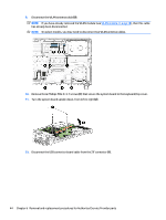
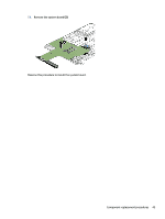
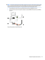
Heat sink (with UMA memory) (select models only) NOTE: The heat sink spare part kit includes replacement thermal material. Description Spare part number For use only on computer models equipped with an Intel Core processor and a graphics subsystem with UMA memory 806826-001 For use only on computer models equipped with an Intel Pentium processor and a graphics subsystem with 809106-001 UMA memory IMPORTANT: Make special note of each screw and screw lock size and location during removal and replacement. Before removing the heat sink, follow these steps: 1. Shut down the computer. 2. Disconnect all external devices connected to the computer. 3. Disconnect the power from the computer by first unplugging the power cord from the AC outlet and then unplugging the AC adapter from the computer. 4. Remove the battery (see Battery on page 29), and then remove the following components: a. Optical drive (see Optical drive on page 30). b. Base enclosure (see Base enclosure on page 33). Remove the heat sink: 1. Loosen the six Phillips PM2.0×4.0 captive screws (1) that secure the heat sink to the system board. CAUTION: Screws should be loosened in the order embossed on the heat sink plates. Failing to remove the screws in this order could damage the computer's processor or video components. 2. Lift heat sink away from system board (2). NOTE: Due to the adhesive quality of the thermal material located between the heat sink and the system board components, it may be necessary to move the heat sink from side to side to detach it. 48 Chapter 6 Removal and replacement procedures for Authorized Service Provider parts
-
 1
1 -
2
-
3
-
4
-
5
-
6
-
7
-
8
-
9
-
10
-
11
-
12
-
13
-
14
-
15
-
16
-
17
-
18
-
19
-
20
-
21
-
22
-
23
-
24
-
25
-
26
-
27
-
28
-
29
-
30
-
31
-
32
-
33
-
34
-
35
-
36
-
37
-
38
-
39
-
40
-
41
-
42
-
43
-
44
-
45
-
46
-
47
-
48
-
49
-
50
-
51
-
52
-
 53
53 -
 54
54 -
 55
55 -
 56
56 -
 57
57 -
 58
58 -
 59
59 -
 60
60 -
 61
61 -
 62
62 -
 63
63 -
64
-
65
-
66
-
67
-
68
-
69
-
70
-
71
-
72
-
73
-
74
-
75
-
76
-
77
-
78
-
79
-
80
-
81
-
82
-
83
-
84
-
85
-
86
-
87
-
88
-
89
-
90
-
91
-
92
-
93
-
94
-
95
-
96
-
97
-
98
-
99
 |
 |
