HP Pavilion 14-ab000 ab000 through 14 - ab099 Maintenance and Service Guide - Page 65
Power button board, Disconnect power connector cable
 |
View all HP Pavilion 14-ab000 manuals
Add to My Manuals
Save this manual to your list of manuals |
Page 65 highlights
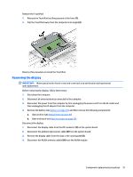
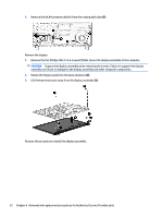
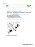
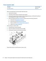
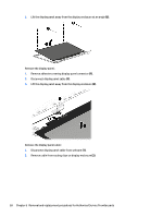
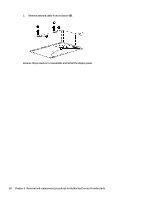
Power button board NOTE: The power button board spare part kit includes the power connector cable. Description Power button board Spare part number 806749-001 IMPORTANT: Make special note of each screw and screw lock size and location during removal and replacement. Before removing the power button board, follow these steps: 1. Shut down the computer. 2. Disconnect all external devices connected to the computer. 3. Disconnect the power from the computer by first unplugging the power cord from the AC outlet and then unplugging the AC adapter from the computer. 4. Remove the battery (see Battery on page 29), and then remove the following components: a. Optical drive (see Optical drive on page 30). b. Base enclosure (see Base enclosure on page 33). c. Display assembly (see Removing the display on page 51). d. Speakers (see Speakers on page 53). e. Power connector cable (see Power connector cable on page 54). Remove the power button board: 1. Disconnect power connector cable (1). 2. Remove the one Phillips PM2×2 broad head screw (2) that secures the board to the keyboard/top cover. 3. Remove the power button board from the base enclosure retention clips (3). 4. Lift the power button board up at an angle and remove from the base enclosure (4). Reverse this procedure to install the power button board. Component replacement procedures 55
-
 1
1 -
2
-
3
-
4
-
5
-
6
-
7
-
8
-
9
-
10
-
11
-
12
-
13
-
14
-
15
-
16
-
17
-
18
-
19
-
20
-
21
-
22
-
23
-
24
-
25
-
26
-
27
-
28
-
29
-
30
-
31
-
32
-
33
-
34
-
35
-
36
-
37
-
38
-
39
-
40
-
41
-
42
-
43
-
44
-
45
-
46
-
47
-
48
-
49
-
50
-
51
-
52
-
53
-
54
-
55
-
56
-
57
-
58
-
59
-
 60
60 -
 61
61 -
 62
62 -
 63
63 -
 64
64 -
 65
65 -
 66
66 -
 67
67 -
 68
68 -
 69
69 -
 70
70 -
71
-
72
-
73
-
74
-
75
-
76
-
77
-
78
-
79
-
80
-
81
-
82
-
83
-
84
-
85
-
86
-
87
-
88
-
89
-
90
-
91
-
92
-
93
-
94
-
95
-
96
-
97
-
98
-
99
 |
 |
