HP Pavilion 14-ab000 ab000 through 14 - ab099 Maintenance and Service Guide - Page 73
that secure the hinges to the display enclosure., Remove the two Phillips PM1.9×3.5 screws
 |
View all HP Pavilion 14-ab000 manuals
Add to My Manuals
Save this manual to your list of manuals |
Page 73 highlights
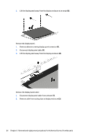
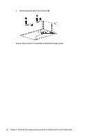
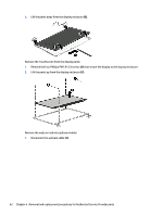
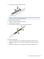
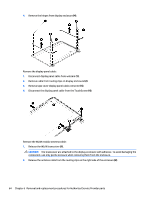
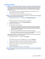
2. Lift the webcam away from the display enclosure (2). CAUTION: The webcam is attached to the display enclosure with adhesive. Use gentle pressure while removing the webcam to avoid breaking the component. Release the TouchScreen interface board: 1. Disconnect the TouchScreen interface board cable (1). 2. Detach the clips from the board (2). 3. Lift the TouchScreen interface board away from the display enclosure (3). Remove the display panel hinges: 1. Remove the two Phillips PM1.9×3.5 screws (1) that secure the hinges to the display enclosure. 2. Remove the four Phillips PM2.5×3.22 broad head screws (2) that secure the hinges to the display enclosure. 3. Remove the two Phillips PM2.4×4.7 screws (3) that secure the hinges to the display enclosure. Component replacement procedures 63
-
 1
1 -
2
-
3
-
4
-
5
-
6
-
7
-
8
-
9
-
10
-
11
-
12
-
13
-
14
-
15
-
16
-
17
-
18
-
19
-
20
-
21
-
22
-
23
-
24
-
25
-
26
-
27
-
28
-
29
-
30
-
31
-
32
-
33
-
34
-
35
-
36
-
37
-
38
-
39
-
40
-
41
-
42
-
43
-
44
-
45
-
46
-
47
-
48
-
49
-
50
-
51
-
52
-
53
-
54
-
55
-
56
-
57
-
58
-
59
-
60
-
61
-
62
-
63
-
64
-
65
-
66
-
67
-
 68
68 -
 69
69 -
 70
70 -
 71
71 -
 72
72 -
 73
73 -
 74
74 -
 75
75 -
 76
76 -
 77
77 -
 78
78 -
79
-
80
-
81
-
82
-
83
-
84
-
85
-
86
-
87
-
88
-
89
-
90
-
91
-
92
-
93
-
94
-
95
-
96
-
97
-
98
-
99
 |
 |
