HP Pavilion dv7-6b00 HP Pavilion dv7 Notebook PC Maintenance and Service Guide - Page 57
Remove the Phillips PM2.5×5.0 screw that secures the optical drive to the computer.
 |
View all HP Pavilion dv7-6b00 manuals
Add to My Manuals
Save this manual to your list of manuals |
Page 57 highlights
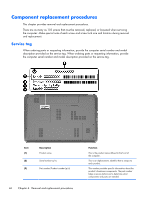
3. Disconnect the power from the computer by first unplugging the power cord from the AC outlet and then unplugging the AC adapter from the computer. 4. Remove the battery (see Battery on page 47). Remove the optical drive: 1. Slide the release latch (1) to release the service cover from the computer. 2. Lift the rear edge of the service cover (2) up and forward until it rests at an angle. 3. Remove the service cover. The service cover is available in the Plastics Kit, spare part number 665604-001. 4. Remove the Phillips PM2.5×5.0 screw that secures the optical drive to the computer. 5. Push on the hard drive bracket (1) to release the optical drive. Component replacement procedures 49
-
 1
1 -
2
-
3
-
4
-
5
-
6
-
7
-
8
-
9
-
10
-
11
-
12
-
13
-
14
-
15
-
16
-
17
-
18
-
19
-
20
-
21
-
22
-
23
-
24
-
25
-
26
-
27
-
28
-
29
-
30
-
31
-
32
-
33
-
34
-
35
-
36
-
37
-
38
-
39
-
40
-
41
-
42
-
43
-
44
-
45
-
46
-
47
-
48
-
49
-
50
-
51
-
 52
52 -
 53
53 -
 54
54 -
 55
55 -
 56
56 -
 57
57 -
 58
58 -
 59
59 -
 60
60 -
 61
61 -
 62
62 -
63
-
64
-
65
-
66
-
67
-
68
-
69
-
70
-
71
-
72
-
73
-
74
-
75
-
76
-
77
-
78
-
79
-
80
-
81
-
82
-
83
-
84
-
85
-
86
-
87
-
88
-
89
-
90
-
91
-
92
-
93
-
94
-
95
-
96
-
97
-
98
-
99
-
100
-
101
-
102
-
103
-
104
-
105
-
106
-
107
-
108
-
109
-
110
-
111
-
112
-
113
-
114
-
115
-
116
-
117
-
118
-
119
-
120
-
121
-
122
-
123
-
124
-
125
-
126
-
127
-
128
-
129
-
130
-
131
-
132
-
133
-
134
-
135
 |
 |

3.
Disconnect the power from the computer by first unplugging the power cord from the AC outlet
and then unplugging the AC adapter from the computer.
4.
Remove the battery (see
Battery
on page
47
).
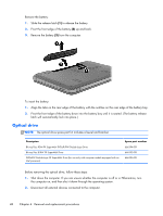
Remove the optical drive:
1.
Slide the release latch
(1)
to release the service cover from the computer.
2.
Lift the rear edge of the service cover
(2)
up and forward until it rests at an angle.
3.
Remove the service cover. The service cover is available in the Plastics Kit, spare part number
665604-001.
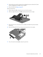
4.
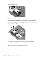
Remove the Phillips PM2.5×5.0 screw that secures the optical drive to the computer.
5.
Push on the hard drive bracket
(1)
to release the optical drive.
Component replacement procedures
49