HP Pavilion dv7-6b00 HP Pavilion dv7 Notebook PC Maintenance and Service Guide - Page 72
in the top cover., through the opening
 |
View all HP Pavilion dv7-6b00 manuals
Add to My Manuals
Save this manual to your list of manuals |
Page 72 highlights
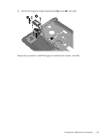
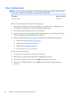
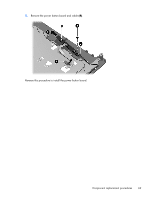
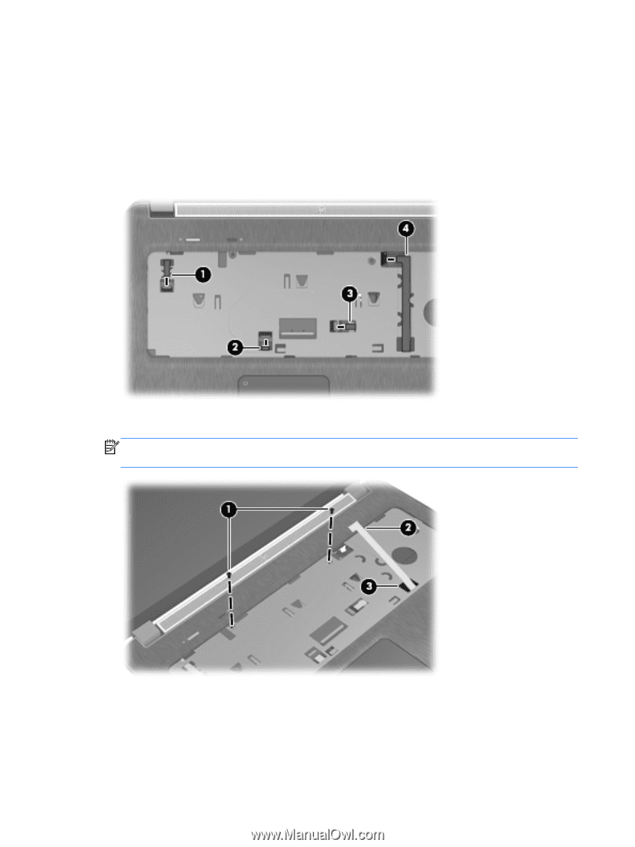
7. Release the ZIF connectors to which the following cables are attached, and then disconnect the cables from the system board: (1) Power button board cable (2) TouchPad button board cable (3) Fingerprint reader board cable (4) USB board cable 8. Remove the two Phillips PM2.5×5.0 screws that secure the top cover to the computer. NOTE: As you prepare to release the top cover, make sure the USB board (2) cable feeds freely through the opening (3) in the top cover. 9. Lift the rear edge of the top cover (1) until the left and right sides disengage from the base enclosure. 64 Chapter 4 Removal and replacement procedures
-
 1
1 -
2
-
3
-
4
-
5
-
6
-
7
-
8
-
9
-
10
-
11
-
12
-
13
-
14
-
15
-
16
-
17
-
18
-
19
-
20
-
21
-
22
-
23
-
24
-
25
-
26
-
27
-
28
-
29
-
30
-
31
-
32
-
33
-
34
-
35
-
36
-
37
-
38
-
39
-
40
-
41
-
42
-
43
-
44
-
45
-
46
-
47
-
48
-
49
-
50
-
51
-
52
-
53
-
54
-
55
-
56
-
57
-
58
-
59
-
60
-
61
-
62
-
63
-
64
-
65
-
66
-
 67
67 -
 68
68 -
 69
69 -
 70
70 -
 71
71 -
 72
72 -
 73
73 -
 74
74 -
 75
75 -
 76
76 -
 77
77 -
78
-
79
-
80
-
81
-
82
-
83
-
84
-
85
-
86
-
87
-
88
-
89
-
90
-
91
-
92
-
93
-
94
-
95
-
96
-
97
-
98
-
99
-
100
-
101
-
102
-
103
-
104
-
105
-
106
-
107
-
108
-
109
-
110
-
111
-
112
-
113
-
114
-
115
-
116
-
117
-
118
-
119
-
120
-
121
-
122
-
123
-
124
-
125
-
126
-
127
-
128
-
129
-
130
-
131
-
132
-
133
-
134
-
135
 |
 |
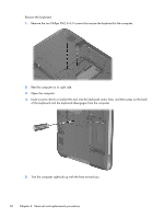
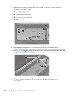
7.
Release the ZIF connectors to which the following cables are attached, and then disconnect
the cables from the system board:
(1)
Power button board cable
(2)
TouchPad button board cable
(3)
Fingerprint reader board cable
(4)
USB board cable
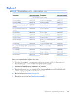
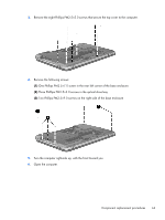
8.
Remove the two Phillips PM2.5×5.0 screws that secure the top cover to the computer.
NOTE:
As you prepare to release the top cover, make sure the USB board
(2)
cable feeds freely
through the opening
(3)
in the top cover.
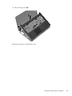
9.
Lift the rear edge of the top cover
(1)
until the left and right sides disengage from the
base enclosure.
64
Chapter 4
Removal and replacement procedures