HP Pavilion dv7-6b00 HP Pavilion dv7 Notebook PC Maintenance and Service Guide - Page 92
openings in the base enclosure., of the base enclosure outward to allow the audio connectors
 |
View all HP Pavilion dv7-6b00 manuals
Add to My Manuals
Save this manual to your list of manuals |
Page 92 highlights
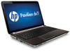
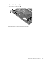
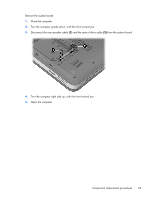
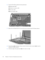
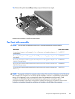
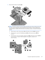
6. Disconnect the following cables from the system board: (1) Display panel cable (2) Webcam/microphone cable (3) Subwoofer cable (4) Power connector cable 7. Remove the five Phillips PM2.5×5.0 screws that secure the system board to the base enclosure. 8. Flex the left side (1) of the base enclosure outward to allow the audio connectors (2) to clear the openings in the base enclosure. 9. Lift the front edge of the system board (3) until it rests at an angle. 84 Chapter 4 Removal and replacement procedures
-
 1
1 -
2
-
3
-
4
-
5
-
6
-
7
-
8
-
9
-
10
-
11
-
12
-
13
-
14
-
15
-
16
-
17
-
18
-
19
-
20
-
21
-
22
-
23
-
24
-
25
-
26
-
27
-
28
-
29
-
30
-
31
-
32
-
33
-
34
-
35
-
36
-
37
-
38
-
39
-
40
-
41
-
42
-
43
-
44
-
45
-
46
-
47
-
48
-
49
-
50
-
51
-
52
-
53
-
54
-
55
-
56
-
57
-
58
-
59
-
60
-
61
-
62
-
63
-
64
-
65
-
66
-
67
-
68
-
69
-
70
-
71
-
72
-
73
-
74
-
75
-
76
-
77
-
78
-
79
-
80
-
81
-
82
-
83
-
84
-
85
-
86
-
 87
87 -
 88
88 -
 89
89 -
 90
90 -
 91
91 -
 92
92 -
 93
93 -
 94
94 -
 95
95 -
 96
96 -
 97
97 -
98
-
99
-
100
-
101
-
102
-
103
-
104
-
105
-
106
-
107
-
108
-
109
-
110
-
111
-
112
-
113
-
114
-
115
-
116
-
117
-
118
-
119
-
120
-
121
-
122
-
123
-
124
-
125
-
126
-
127
-
128
-
129
-
130
-
131
-
132
-
133
-
134
-
135
 |
 |
6.
Disconnect the following cables from the system board:
(1)
Display panel cable
(2)
Webcam/microphone cable
(3)
Subwoofer cable
(4)
Power connector cable
7.
Remove the five Phillips PM2.5×5.0 screws that secure the system board to the base enclosure.
8.
Flex the left side
(1)
of the base enclosure outward to allow the audio connectors
(2)
to clear the
openings in the base enclosure.
9.
Lift the front edge of the system board
(3)
until it rests at an angle.
84
Chapter 4
Removal and replacement procedures