HP Pavilion dv7-6b00 HP Pavilion dv7 Notebook PC Maintenance and Service Guide - Page 93
Fan/heat sink assembly
 |
View all HP Pavilion dv7-6b00 manuals
Add to My Manuals
Save this manual to your list of manuals |
Page 93 highlights
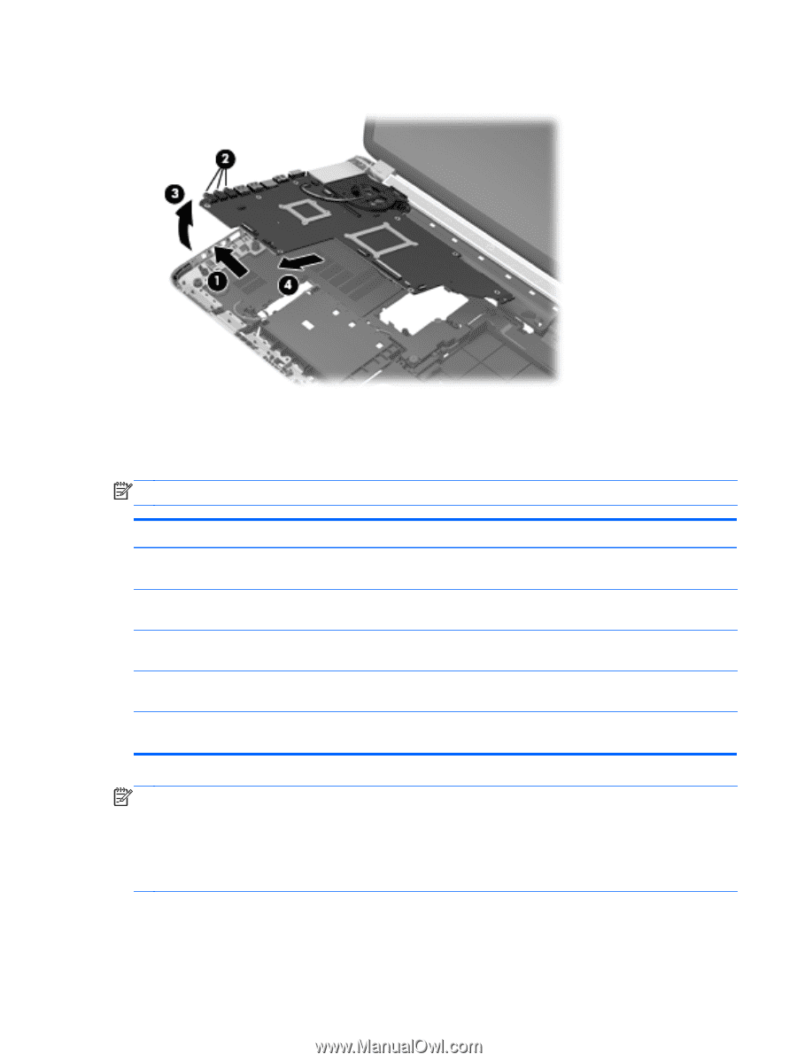
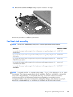
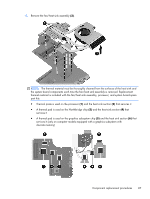
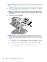
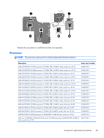
10. Remove the system board (4) by sliding it up and forward at an angle. Reverse this procedure to install the system board. Fan/heat sink assembly NOTE: The fan/heat sink assembly spare part kit includes replacement thermal material. Description Spare part number For use only with computer models equipped with an AMD processor and a graphics subsystem with 666527-001 discrete memory For use only with computer models equipped with an AMD processor and a graphics subsystem with 666526-001 UMA memory For use only with computer models equipped with an Intel processor and a graphics subsystem with 2048-MB of discrete memory 666391-001 For use only with computer models equipped with an Intel processor and a graphics subsystem with 1024-MB of discrete memory 666390-001 For use only with computer models equipped with an Intel processor and a graphics subsystem with UMA memory 666392-001 NOTE: To properly ventilate the computer, allow at least 7.6 cm (3 in) of clearance on the left side of the computer. The computer uses an electric fan for ventilation. The fan is controlled by a temperature sensor and is designed to turn on automatically when high temperature conditions exist. These conditions are affected by high external temperatures, system power consumption, power management/battery conservation configurations, battery fast charging, and software requirements. Exhaust air is displaced through the ventilation grill located on the left side of the computer. Component replacement procedures 85
-
 1
1 -
2
-
3
-
4
-
5
-
6
-
7
-
8
-
9
-
10
-
11
-
12
-
13
-
14
-
15
-
16
-
17
-
18
-
19
-
20
-
21
-
22
-
23
-
24
-
25
-
26
-
27
-
28
-
29
-
30
-
31
-
32
-
33
-
34
-
35
-
36
-
37
-
38
-
39
-
40
-
41
-
42
-
43
-
44
-
45
-
46
-
47
-
48
-
49
-
50
-
51
-
52
-
53
-
54
-
55
-
56
-
57
-
58
-
59
-
60
-
61
-
62
-
63
-
64
-
65
-
66
-
67
-
68
-
69
-
70
-
71
-
72
-
73
-
74
-
75
-
76
-
77
-
78
-
79
-
80
-
81
-
82
-
83
-
84
-
85
-
86
-
87
-
 88
88 -
 89
89 -
 90
90 -
 91
91 -
 92
92 -
 93
93 -
 94
94 -
 95
95 -
 96
96 -
 97
97 -
 98
98 -
99
-
100
-
101
-
102
-
103
-
104
-
105
-
106
-
107
-
108
-
109
-
110
-
111
-
112
-
113
-
114
-
115
-
116
-
117
-
118
-
119
-
120
-
121
-
122
-
123
-
124
-
125
-
126
-
127
-
128
-
129
-
130
-
131
-
132
-
133
-
134
-
135
 |
 |