HP Pavilion dv7-6b00 HP Pavilion dv7 Notebook PC Maintenance and Service Guide - Page 94
Steps 3 and 4 apply to computer models equipped with an AMD processor. See steps 5
 |
View all HP Pavilion dv7-6b00 manuals
Add to My Manuals
Save this manual to your list of manuals |
Page 94 highlights
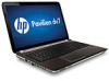
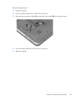
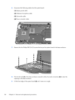
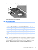
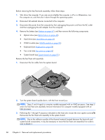
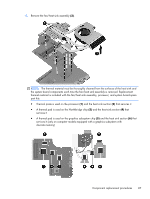
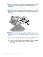
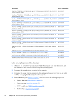
Before removing the fan/heat sink assembly, follow these steps: 1. Shut down the computer. If you are unsure whether the computer is off or in Hibernation, turn the computer on, and then shut it down through the operating system. 2. Disconnect all external devices connected to the computer. 3. Disconnect the power from the computer by first unplugging the power cord from the AC outlet and then unplugging the AC adapter from the computer. 4. Remove the battery (see Battery on page 47), and then remove the following components: ● Optical drive (see Optical drive on page 48) ● Hard drive (see Hard drive on page 51) ● WLAN module (see WLAN module on page 56) ● Keyboard (see Keyboard on page 59) ● Top cover (see Top cover on page 62) ● System board (see System board on page 81) Remove the fan/heat sink assembly: 1. Disconnect the fan cable from the system board. 2. Turn the system board upside down, with the front toward you. NOTE: Steps 3 and 4 apply to computer models equipped with an AMD processor. See steps 5 and 6 for fan/heat sink assembly removal information for computer models equipped with an Intel processor. 3. Following the 1 through 9 sequence indicated on the heat sink, loosen the nine captive screws (1) that secure the fan/heat sink assembly to the system board. NOTE: Due to the adhesive quality of the thermal material located between the heat sink and system board components, it may be necessary to move the fan/heat sink assembly from side to side to detach it. 86 Chapter 4 Removal and replacement procedures
-
 1
1 -
2
-
3
-
4
-
5
-
6
-
7
-
8
-
9
-
10
-
11
-
12
-
13
-
14
-
15
-
16
-
17
-
18
-
19
-
20
-
21
-
22
-
23
-
24
-
25
-
26
-
27
-
28
-
29
-
30
-
31
-
32
-
33
-
34
-
35
-
36
-
37
-
38
-
39
-
40
-
41
-
42
-
43
-
44
-
45
-
46
-
47
-
48
-
49
-
50
-
51
-
52
-
53
-
54
-
55
-
56
-
57
-
58
-
59
-
60
-
61
-
62
-
63
-
64
-
65
-
66
-
67
-
68
-
69
-
70
-
71
-
72
-
73
-
74
-
75
-
76
-
77
-
78
-
79
-
80
-
81
-
82
-
83
-
84
-
85
-
86
-
87
-
88
-
 89
89 -
 90
90 -
 91
91 -
 92
92 -
 93
93 -
 94
94 -
 95
95 -
 96
96 -
 97
97 -
 98
98 -
 99
99 -
100
-
101
-
102
-
103
-
104
-
105
-
106
-
107
-
108
-
109
-
110
-
111
-
112
-
113
-
114
-
115
-
116
-
117
-
118
-
119
-
120
-
121
-
122
-
123
-
124
-
125
-
126
-
127
-
128
-
129
-
130
-
131
-
132
-
133
-
134
-
135
 |
 |