HP ProBook 6360b HP ProBook 6360b Notebook PC - Maintenance and Service Guide - Page 100
CAUTION, If it is necessary to replace the display bezel or display hinges, remove the following
 |
View all HP ProBook 6360b manuals
Add to My Manuals
Save this manual to your list of manuals |
Page 100 highlights
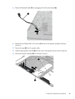
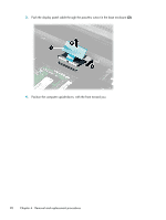
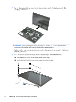
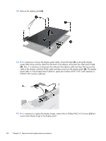
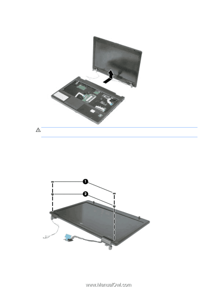
7. Pull the display assembly out away from the base enclosure and lift the display assembly (1) straight up and remove it. CAUTION: When installing the display assembly, be sure that the wireless antenna cables routed out of the display right hinge are routed and arranged properly. Failure to follow these routing instructions can result in degradation of the computer's WLAN and WWAN performance. 8. If it is necessary to replace the display bezel or display hinges, remove the following: (1) Two rubber screw covers on the display bezel bottom edge (2) Two Phillips PM2.5×5.0 screws on the display bezel bottom edge 92 Chapter 4 Removal and replacement procedures
-
 1
1 -
2
-
3
-
4
-
5
-
6
-
7
-
8
-
9
-
10
-
11
-
12
-
13
-
14
-
15
-
16
-
17
-
18
-
19
-
20
-
21
-
22
-
23
-
24
-
25
-
26
-
27
-
28
-
29
-
30
-
31
-
32
-
33
-
34
-
35
-
36
-
37
-
38
-
39
-
40
-
41
-
42
-
43
-
44
-
45
-
46
-
47
-
48
-
49
-
50
-
51
-
52
-
53
-
54
-
55
-
56
-
57
-
58
-
59
-
60
-
61
-
62
-
63
-
64
-
65
-
66
-
67
-
68
-
69
-
70
-
71
-
72
-
73
-
74
-
75
-
76
-
77
-
78
-
79
-
80
-
81
-
82
-
83
-
84
-
85
-
86
-
87
-
88
-
89
-
90
-
91
-
92
-
93
-
94
-
 95
95 -
 96
96 -
 97
97 -
 98
98 -
 99
99 -
 100
100 -
 101
101 -
 102
102 -
 103
103 -
 104
104 -
 105
105 -
106
-
107
-
108
-
109
-
110
-
111
-
112
-
113
-
114
-
115
-
116
-
117
-
118
-
119
-
120
-
121
-
122
-
123
-
124
-
125
-
126
-
127
-
128
-
129
-
130
-
131
-
132
-
133
-
134
-
135
-
136
-
137
-
138
-
139
-
140
-
141
-
142
-
143
-
144
-
145
-
146
-
147
-
148
-
149
-
150
-
151
-
152
-
153
-
154
-
155
-
156
-
157
 |
 |
7.
Pull the display assembly out away from the base enclosure and lift the display assembly
(1)
straight up and remove it.
CAUTION:
When installing the display assembly, be sure that the wireless antenna cables
routed out of the display right hinge are routed and arranged properly.
Failure to follow these routing instructions can result in degradation of the computer's WLAN and
WWAN performance.
8.
If it is necessary to replace the display bezel or display hinges, remove the following:
(1)
Two rubber screw covers on the display bezel bottom edge
(2)
Two Phillips PM2.5×5.0 screws on the display bezel bottom edge
92
Chapter 4
Removal and replacement procedures